About Tom Heiber

Software Developer Consultant Car Nut Tech Geek

iPXE on Dell C6100 (BIOS Mod)

My step by step instructions on modifying the Dell PowerEdge C6100 BIOS firmware to replace the stock Intel iSCSI/PXE bootloader with the much more versatile iPXE firmware. Some of iPXE features include boot from ATA over Ethernet, FCoE, Infiniband network, HTTP web server and of course iSCSI. It supports an advanced scripting environment that can alter the boot process by simply uplading a new script file to a web server or TFTP server among others. A huge improvement over the standard Intel PXE loader.

This is a non-standard, risky procedure because we’re modifying embedded network interfaces and not add-on cards. The goal is to have the Dell C6100 as a completely diskless system with the ability to boot from various sources over the network without having to be physically at the server.

ipxe2

First the usual disclaimer: I hold no responsibility if you hose your motherboard doing this. Anything in this article is very far from “supported operation”. Just because it worked for me, doesn’t guarantee that it’ll work for you.

With that out of the way…

The ROM that I’ll be building will be capable of chain loading a dynamic PXE/iSCSI script from a TFTP server. script file will be unique to each server as the script filename will be based on the MAC address of the iPXE interface.

If you want to skip building the whole thing yourself, you can just download the ROM file. All files referenced in this doc are at the end of this post.

Prerequisites:

  • Flash BIOS to the latest version. 1.7 in my case.
  • Enable Option ROM in BIOS for the Network cards
  • Linux machine with gcc/make environment to build our iPXE ROM
  • Windows machine to modify the stock C6100 BIOS and inject the iPXE firmware
  • Bootable USB stick to flash the firmware

In order to build the proper ROM firmware we need to identify the specific Vendor ID and Device ID. To do this simply boot a Linux Live CD on the C6100 and issue the “lspci” command to show all devices

[root@localhost ~]# lspci
00:00.0 Host bridge: Intel Corporation 5500 I/O Hub to ESI Port (rev 22)
00:01.0 PCI bridge: Intel Corporation 5520/5500/X58 I/O Hub PCI Express Root Port 1 (rev 22)
00:03.0 PCI bridge: Intel Corporation 5520/5500/X58 I/O Hub PCI Express Root Port 3 (rev 22)
00:07.0 PCI bridge: Intel Corporation 5520/5500/X58 I/O Hub PCI Express Root Port 7 (rev 22)
00:13.0 PIC: Intel Corporation 7500/5520/5500/X58 I/O Hub I/OxAPIC Interrupt Controller (rev 22)
00:14.0 PIC: Intel Corporation 7500/5520/5500/X58 I/O Hub System Management Registers (rev 22)
00:14.1 PIC: Intel Corporation 7500/5520/5500/X58 I/O Hub GPIO and Scratch Pad Registers (rev 22)
00:14.2 PIC: Intel Corporation 7500/5520/5500/X58 I/O Hub Control Status and RAS Registers (rev 22)
00:14.3 PIC: Intel Corporation 7500/5520/5500/X58 I/O Hub Throttle Registers (rev 22)
00:16.0 System peripheral: Intel Corporation 5520/5500/X58 Chipset QuickData Technology Device (rev 22)
00:16.1 System peripheral: Intel Corporation 5520/5500/X58 Chipset QuickData Technology Device (rev 22)
00:16.2 System peripheral: Intel Corporation 5520/5500/X58 Chipset QuickData Technology Device (rev 22)
00:16.3 System peripheral: Intel Corporation 5520/5500/X58 Chipset QuickData Technology Device (rev 22)
00:16.4 System peripheral: Intel Corporation 5520/5500/X58 Chipset QuickData Technology Device (rev 22)
00:16.5 System peripheral: Intel Corporation 5520/5500/X58 Chipset QuickData Technology Device (rev 22)
00:16.6 System peripheral: Intel Corporation 5520/5500/X58 Chipset QuickData Technology Device (rev 22)
00:16.7 System peripheral: Intel Corporation 5520/5500/X58 Chipset QuickData Technology Device (rev 22)
00:1d.0 USB controller: Intel Corporation 82801JI (ICH10 Family) USB UHCI Controller #1
00:1d.1 USB controller: Intel Corporation 82801JI (ICH10 Family) USB UHCI Controller #2
00:1d.2 USB controller: Intel Corporation 82801JI (ICH10 Family) USB UHCI Controller #3
00:1d.7 USB controller: Intel Corporation 82801JI (ICH10 Family) USB2 EHCI Controller #1
00:1e.0 PCI bridge: Intel Corporation 82801 PCI Bridge (rev 90)
00:1f.0 ISA bridge: Intel Corporation 82801JIR (ICH10R) LPC Interface Controller
00:1f.2 SATA controller: Intel Corporation 82801JI (ICH10 Family) SATA AHCI Controller
00:1f.3 SMBus: Intel Corporation 82801JI (ICH10 Family) SMBus Controller
01:00.0 Ethernet controller: Intel Corporation 82576 Gigabit Network Connection (rev 01)
01:00.1 Ethernet controller: Intel Corporation 82576 Gigabit Network Connection (rev 01)
05:04.0 VGA compatible controller: ASPEED Technology, Inc. ASPEED Graphics Family (rev 10)

We can see the Ethernet controll is at address 01:00.0. Let’s get some details

[root@localhost ~] lspci -n -s 01:00.0
01:00.0 0200: 8086:10c9 (rev 01)

We have our Vendor and Device ID’s. We combine the two to get our ROM filename, but that will come later.

Now it’s time to set up a build environment. Assuming all the compiler tools are installed on our linux machine, we download the source from the Git repository.

[root@localhost ~] cd /tmp
[root@localhost ~] git clone git://git.ipxe.org/ipxe.git
[root@localhost ~] cd ipxe/src

Upgrading Dell C6100 BIOS

These are my step-by-step instructions how to safely upgrade the Dell PowerEdge C6100 without bricking the nodes.

Couple of points:

  • If your service tag is not on Dell Site, you can not upgrade. Forcing the flash will likely brick your node.
  • Always upgrade the BMC first.
  • BMC must be upgraded on ALL nodes in the chassis
  • These instructions worked for me. I can not be responsible if they do not work for you
  • A lof of steps here might seem unnecessary, please follow anyways
  • There seems to be no difference when a chassis is hosting nodes with mixed BIOS/BMC versions.
  • When flashing a node, the powered state of other nodes doesn’t matter. Can even be removed.

Using the following method, I’ve successfully upgraded the following firmwares:

BMC 1.11 -> 1.32
BMC 1.22 -> 1.32
BMC 1.29 -> 1.32

BIOS 1.44 -> 1.70
BIOS 1.62 -> 1.70
BIOS 1.69 -> 1.70

FCB 1.08 -> 1.20
FCB 1.14 -> 1.20

First thing is first. Need to download the appropriate firmware files from the Dell Support Site here. To find your firmware files, enter your Service Tag number found on the back of the server. If the sticker is missing you can try the BIOS but be warned that not all nodes might be from the same chassis.
c6100bios1

If the DELL site comes up with “Invalid Service Tag” message, STOP RIGHT HERE. Your server is a custom build and it does not support the C6100 firmware from the site. Proceeding will most likely end up in bricking your nodes.

Once the drivers and files show up on the site, download the BIOS, BMC and FCB files.
c6100bios2

Run each downloaded EXE file and extract the files contents to your local drive.
c6100bios3
c6100bios4

Once all files have been extracted. Copy the three folders to a bootable DOS USB stick. There are many ways of making a DOS bootable USB Stick. Use the stick to boot into a DOS prompt.

We’re first going to flash the BMC. This is important because an older BMC might have trouble communicating with a new BIOS, but a new BMC will always support an older BIOS.
To flash the BMC, we’re using the SOCFLASH utility. Flashing is easy. Simply navigate to the SOCFLASH\DOS folder and execute flash8.bat.
IMG_0648

The rest of the BMC flash process is completely automated.
IMG_0650

Once the BMC has been flashed, power cycle the chassis. This means, unplug the server, wait a few seconds and plug it back in. This ensures a complete reset of the BMC. Power up the node and watch closely for POST messages.

If you see an “Error: BMC NOT Responding” message. REBOOT THE NODE.
IMG_0651

A simple soft reboot is enough to re-establish communication with the BMC.
IMG_0643

Once back in the dos prompt. Navigate to the folder where the C6100 BIOS files are located. At this point attempting to flash using the automated FBIOS.bat file will most likely generate a message “Different ROM ID between current system and update BIOS rom file”. This is expected.
IMG_0641

To properly flash the BIOS enter the following command at the prompt

>afudos 6100v170.rom /p /b /n /c /x

Naturally, replace the .rom filename with whatever the current firmware version is. The /X parameter skips the ROM ID check and forces the flash process.
IMG_0644

Once the flash process finishes, reboot the Node (a soft boot will suffice). During the boot process, the F2 (BIOS Entry) option is not displayed. Not sure why that is. Once the boot process finishes, reboot the node one more time to re-enter the BIOS settings.
IMG_0646

Once the BIOS settings are configured. Simply save and exit. At this point the flash process for the node is done and the next node can be flashed. For every remaining node flash both the BMC and BIOS.

Once all the nodes are flash, it might be a good idea to flash the Fan Controller Board. Some earlier firmwares (prior to 1.14) run the fans at much higher speeds than necessary making the server much noisier than it should be. If running the server in a data center this is typically not a problem but definitely makes a difference when running at home. Flashing the Fan Controller is very easy. Simply navigate to the folder on the USB stick where the FCB files are located and run FCB.bat. A quick note. The firmware is only compatible with the PIC-18 controller board. If your server came with the PIC-16 board, you’re out of luck. The firmware can not be flashed and the only way to slow down the fans is either via upgrading the FCB or by swapping the fans for something slower/quieter.
The FCB needs to be only flashed once per chassis. That means once the FCB has been flashed on a single node, the other nodes will see the upgraded firmware.
IMG_0659

And that’s it. The C6100 is now running on latest firmware.

New ZFS Server

I bought a new server to replace my Dell PowerEdge R710. The new server is an HP DL180 G6. Equipped with E5620 CPU and 48GB of RAM.
IMG_0604

The server also came with 12 300GB 15,000 RPM SAS drives. These drives will be split between the server backplane and a Dell PowerVault MD1000 to increase throughput.
IMG_0605

The new server will also act as a backup server, so I’ll add 3 3TB drives in RAIDZ-1 config.

First order of business is to replace the stock HP P400 RAID card with a non-raid HBA. For this, I’ve chosen the popular IBM M1015 SAS card. It’s a great 6Gbps PCIe 2.0 card that can be easily reflashed to plain HBA mode.
IMG_0606

I’ve also added a temporary Intel PRO/1000 Quad port NIC for Round-Robin iSCSI. In the next few weeks this will be replaced with 40Gbps Infiniband card. But that’s not ready yet.
IMG_0607

The stock RAID card has the SFF-8087 connector in the back of the card, the M1015 has the connectors on top.
IMG_0608

Fortunately HP provided enough slack on the cable to reach to the top of the new card.
IMG_0609

Before the M1015 can be used with ZFS (NexentaStor in my case). I need to reflash the card to “IT” firmware. The process is relatively simple.

Download the IT firmware here – This should be compatible with any LSI SAS2008 based card.

1. Extract the contents of the RAR file to a DOS bootable USB Flash drive.
2. Boot the server using the flash drive. Make sure only one card is connected.

3. Clear the firmware from the card

> megarec -writesbr 0 empty.bin

4. Erase the flash

> megarec -cleanflash 0

5. Reboot the box.
6. Flash the new IT Firmware to the card

> sas2flsh -o -f 2108it.bin -b mptsas2.rom

7. Enable the card’s IT mode. “500605bxxxxxxxxx” SAS address from sticker on the card without dash or quotes.

> sas2flsh -o -sasadd 500605bxxxxxxxxx

8. Final reboot and the card is good to go.

Last step is to rack up the server, populate the drives and install NexentaStor.
IMG_0613

Once NexentaStor is installed. Create the proper DataSets and we’re done. In current config running 14x300GB drives in Mirrored groups giving me about 2TB of usable, high performance storage.
nexenta

New Mail Server – The Search

Looking to set up a new mail server. Currently running Exchange Server but it’s a pain to manage multiple domains. Spam filtering not great. I have few dozen domains and I’d like to consolidate them. I need an easy to use and manage server where I don’t have to spend too much time on it.

Required Features:

* Free (or really cheap)
* Webmail
* Push via Activesync or IMAP Idle
* Anti-Spam Filtering
* Multi-Domain / Aliases
* All-In-One Solution
* Web Based Admin / No manual file editing

Ability to easily create email aliases, great for registering at web sites. Also to determine which web site is selling email addresses.

Product Free WebMail Anti-Spam Push Notes
Axigen Almost Free (100 User Limit) Yes No* No* * Available in full version
Kolab 3.0 Free ? ? ? Failed to install
hMailServer Free No Yes Yes (IMAP Idle) No web admin
SoGo Free ? ? ? Steep learning curve
Blue Mind Free Yes No ? Missing features
Horde Free ? ? ? Steep learning curve
Zimbra Community Free Yes Yes Yes Worth a second look
Synovel Collabsuite Free Yes Yes ? Not sure if Push works

It’s quite a list but I wanted to make sure I touch on all the popular products.

First thing’s first. Configure a Virtual Machine for testing. Most of the products are Linux based, and I’m fine with that but some products run only under Windows so a Windows VM will also be required.

CentosInstall

Once both VM’s were configured and all the updates have been installed I took a snapshot of each VM to make moving onto the next product easy.

WinInstall

I also created a local hosts entry to see how the product responds accessed “remotely”

# Copyright (c) 1993-2009 Microsoft Corp.
#
# This is a sample HOSTS file used by Microsoft TCP/IP for Windows.
#
# This file contains the mappings of IP addresses to host names. Each
# entry should be kept on an individual line. The IP address should
# be placed in the first column followed by the corresponding host name.
# The IP address and the host name should be separated by at least one
# space.
#
# Additionally, comments (such as these) may be inserted on individual
# lines or following the machine name denoted by a '#' symbol.
#
# For example:
#
#      102.54.94.97     rhino.acme.com          # source server
#       38.25.63.10     x.acme.com              # x client host

# localhost name resolution is handled within DNS itself.
#	127.0.0.1       localhost
#	::1             localhost

192.168.77.35 linux.mailtest.com
192.168.77.36 windows.mailtest.com

On To Testing

Upgrading Force10 S50

I picked up another Force10 S50 switch from eBay. This one will be going to the datacenter to replace a couple of Dell switches.

IMG_0601

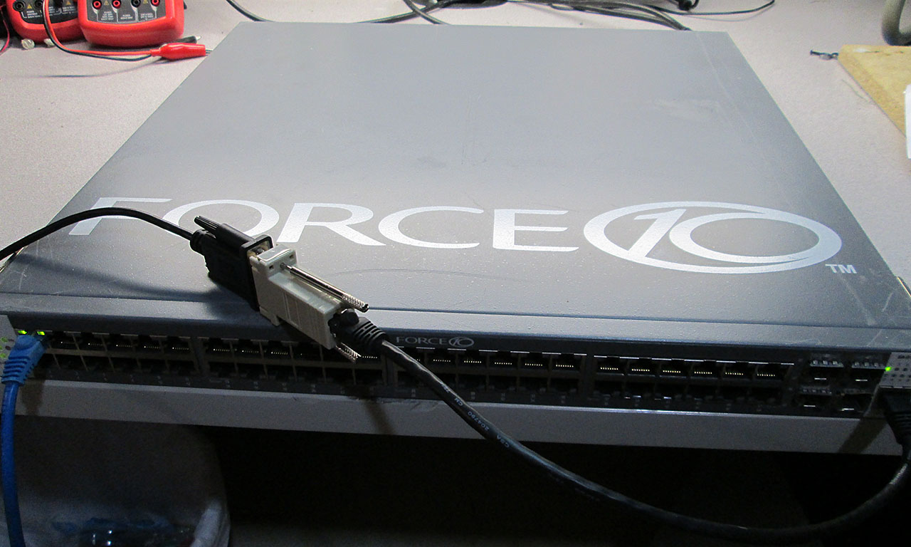
First thing’s first. Need to configure the switch for remote management. Let’s see what we got.

Force10 Boot Code...
Version 01.00.25 05/12/2005

Select an option. If no selection in 2 seconds then
operational code will start.

1 - Start operational code.
2 - Start Boot Menu.
Select (1, 2):2


Boot Menu Version 01.00.25 05/12/2005


Options available
1 - Start operational code
2 - Change baud rate
3 - Retrieve event log using XMODEM (64KB).
4 - Load new operational code using XMODEM
5 - Display operational code vital product data
6 - Update Boot Code
7 - Delete operational code
8 - Reset the system
9 - Restore Configuration to factory defaults (delete config files)
[Boot Menu]

Hmm. That’s a pretty old version of the boot code. In any case, I needed to reset the switch to factory in order to clear the admin password. Once the switch finished booting I went on to see what’s it running.

(Force10 S50) #show hardware

Switch: 1

System Description............................. Force10 S50
Vendor ID...................................... 07
Plant ID....................................... 01
Country Code................................... 04
Date Code...................................... 072005
Serial Number.................................. DE4526001
Part Number.................................... 759-00001-00
Revision....................................... 0A
Catalog Number................................. SA-01-GE-48T
Burned In MAC Address.......................... 00:01:E8:D5:A2:A0
Software Version............................... 2.1.4

Additional Packages............................ Force10 QOS
                                                Force10 Stacking

Eek! That’s a pretty old version of the SFTOS firmware. In fact it’s one of the first, if not the first release for the S50. Really need to upgrade it to something a bit more recent. This actually turned out to be much bigger deal than I anticipated. Force10 site seems to be of no help trying to find an updated firmware for this box. After a LOT of Googling, I finally stumbled upon a 2.5.1 .bin file on an IBM ftp site. That’s the only image I have found after hours of searching. While not the latest version it sure is a big step up from the current 2.1.4 SFTOS.

SFTOS-SA-2.5.1.3

Of course there was no way for me to verify that this image is in fact legitimate, and there was a high risk of bricking the switch if the image wasn’t up to par. But I decided to risk it and go ahead with the upgrade.

First thing’s first. Need to configure networking on the switch in order to TFTP the bin file to it from my workstation. The config process is quite different in 2.1.4 than in 2.5.3 but after a bit of research, I found the proper commands.


User:admin
Password:
(Force10 S50) >enable
Password:

(Force10 S50) #network parms 192.168.77.248 255.255.255.0 192.168.77.1

(Force10 S50) #network mgmt_vlan 1

(Force10 S50) #show network

IP Address..................................... 192.168.77.248
Subnet Mask.................................... 255.255.255.0
Default Gateway................................ 192.168.77.1
Burned In MAC Address.......................... 00:01:E8:D5:A2:A0
Locally Administered MAC Address............... 00:00:00:00:00:00
MAC Address Type............................... Burned In
Network Configuration Protocol Current......... None
Management VLAN ID............................. 1
Web Mode....................................... Disable
Java Mode...................................... Disable

(Force10 S50) #config

(Force10 S50) (Config)#interface 1/0/1

(Force10 S50) (Interface 1/0/1)#vlan participation include 1

(Force10 S50) (Interface 1/0/1)#no shutdown

(Force10 S50) (Interface 1/0/1)#exit

(Force10 S50) (Config)#exit

(Force10 S50) #ping 192.168.77.6

Send count=3, Receive count=3 from 192.168.77.6

Once I confirmed the switch is on the network. It was time to send up the .bin file. I configured a tftp server on my workstation and copied/renamed the bin to sftos.bin to save myself some typing.


(Force10 S50) #copy tftp://192.168.77.6/sftos.bin system:image

Mode........................................... TFTP
Set TFTP Server IP............................. 192.168.77.6
TFTP Path......................................
TFTP Filename.................................. sftos.bin
Data Type...................................... Code

Are you sure you want to start? (y/n) y

TFTP code transfer starting

TFTP receive complete... storing in Flash File System...


File transfer operation completed successfully.

The copying process took only a few seconds. Took a few minutes to store the File in Flash. Now for the main part. Reboot the switch and hope that the new image will take. At the end of this either the switch will work or it’ll be an expensive paper weight.

(Force10 S50) #reload

Management switch has unsaved changes.
Would you like to save them now? (y/n) n

Configuration Not Saved!
Are you sure you want to reload the stack? (y/n) y


Reloading all switches.

Force10 Boot Code...

tffsDevCreate failed.

Storing configuration files
Storing Code base
usrTffsConfig returned 0xffffffff, formatting...
Calling FORMAT ROUTINE

The switch was formatting for quite a long time. After a while I was pretty sure the switch was hosed, but decided to stick it out and see if it comes back. Sure enough, few more minutes later the rest of the upgrade process completed.

Format routine returned with status 0x0
Recover configuration files
CPU Card ID:   0x508245
dimInitialize returned 3
adding the default image - code.bin to the list
dimImageAdd returned -3
Boot Menu Version: 30 Aug 2006
Version 02.01.43 08/30/2006

Select an option. If no selection in 2 seconds then
operational code will start.

1 - Start operational code.
2 - Start Boot Menu.
Select (1, 2):


Operational Code Date: Thu Jan 11 02:38:37 2007
Uncompressing.....

                       50%                     100%
||||||||||||||||||||||||||||||||||||||||||||||||||
Attaching interface lo0...done

Adding 40920 symbols for standalone.
PCI device attached as unit 0.
PCI device attached as unit 1.
PCI device attached as unit 2.
PCI device attached as unit 3.
PCI device attached as unit 4.
Configuring CPUTRANS TX
Configuring CPUTRANS RX
MonitorTask - Active
ConsoleDebugger - Disabled

(Unit 1)>STACK: master on 0:1:e8:d5:a2:a0 (1 cpu, 5 units)
STACK: attach 5 units on 1 cpu
This switch is manager of the stack.


User:

  ******* Binary configuration file detected, migration in progress....  *******
  ******* To prevent loss of data, DO NOT POWER OFF MACHINE!             *******
  ******* Migration to text configuration file completed.                *******
Saved Configuration being applied...Please Wait....

  ******* Applying text configuration.                                   *******

  ******* The following lines in "startup-config" failed execution:
  ******* Line 12:: logging facility -À
  ******* Line 14:: logging history 5595
  ******* Line 15:: logging history size 838875251

User:
  ******* Finished text configuration                                    *******

So, that looked like it worked. Let’s reboot the box and see if all is well.


User:admin
Password:

Force10-S50>enable
Password:

Force10-S50#reload

Are you sure you want to reload the stack?(y/n) y


Reloading all switches.
Calling hardware API to reset the box....
If system doesn't reset within 1 minute, hardware might have become faulty....

.............................................................................................................................................................................................................................................................................................................................................................................................................................................................................................................................................................................................................................................................................................................................................................................................................................................................................................................................................................................................................................................................................................................................................................................................................................................................................................................................................................................................................................................................................................................................................................................................................................................................................................................................................................................................................................................................................................................................................................................................................................................................................................................................................................................................................................................................................................................................................................................................................................................................................................................................................................................................................................................................................................................................................................................................................................................................................................................................................................................................................................................................................................................................................................................................................................................................................................................................................................................................................................

Force10 Boot Code...


CPU Card ID:   0x508245
Boot Menu Version: 30 Aug 2006
2Version 02.01.43 08/30/2006

Select an option. If no selection in 2 seconds then
operational code will start.

1 - Start operational code.
2 - Start Boot Menu.
Select (1, 2):2


Boot Menu Version: 30 Aug 2006

Options available
1  - Start operational code
2  - Change baud rate
3  - Retrieve event log using XMODEM
4  - Load new operational code using XMODEM
5  - Display operational code vital product data
6  - Run flash diagnostics
7  - Update boot code
8  - Delete operational code
9  - Reset the system
10 - Restore configuration to factory defaults (delete config files)
11 - Activate Backup Image
[Boot Menu] 10
[Boot Menu] 9

Are you SURE you want to reset the system? (y/n):y

Calling hardware API to reset the box....

Eureka! We’re good to go. Switch seems healthy and fully functional. Out of curiosity I wanted to see what features came with the image downloaded from the IBM site.

User:admin
Password:
Force10-S50>enable
Password:

Force10-S50#show hardware

Switch: 1

System Description............................. Force10-S50 48GE 2TENGIG L3 Stackable switch
Vendor ID...................................... 07
Plant ID....................................... 01
Country Code................................... 04
Date Code...................................... 072005
Serial Number.................................. DE4526001
Part Number.................................... 759-00001-00
Revision....................................... 0A
Catalog Number................................. SA-01-GE-48T
Burned In MAC Address.......................... 00:01:E8:D5:A2:A0
Software Version............................... 2.5.1.3

Additional Packages............................ Force10 QOS
                                                Force10 Multicast
                                                Force10 Stacking
                                                Force10 Routing

Pluggable Modules and Transceivers:
 None

--More-- or (q)uit
Force10-S50#

Ah. That’s much better. Not only it’s running great the new image adds few more features including L3 routing. Not too shabby.

Now the switch is ready to be configured as per my earlier post here.

How to bring down a rack in just few quick easy steps.

Note to self. pfSense full + SSD = Not Good.

Had a bit of a kerfuffle over the long weekend. Was working remotely on a firewall trying to get NAT through VPN working properly, the firewall didn’t appear to work as it should so I decided to reboot it to make sure all routes are clear. Turns out it was a bad idea. The firewall failed to come back up which resulted in a 100km/drive to the data center to investigate the issue.

When I got there, I quickly plugged in a monitor to the 1U server acting as the firewall and was greeted by a nice “Boot Disk Failure” error on the screen. Good thing I brought a spare firewall, one of my modified Watchguard x750e’s. A quick swap and few minutes later the new firewall was running a restore script on the Watchguard (thanks to a config backup).

Back at home a little digging showed that non-embedded version of pfSense do not play nicely with SSD’s. Especially if RRD is installed. Turns out that RRD writes out new traffic images to physical disk every minute. Multiply that by 8 months and that’s a lot of writes to an SSD that doesn’t support write leveling.

Lesson learned. I bought a couple more Watchguard x750e’s from eBay. One to serve as a replacement at another data center, which is also running installed pfSense on a PC/SSD combo and another Firebox as a warm spare.

New Web Site

Been spending some free time lately learning some new technologies and improving my knowledge of others.

End result: http://www.jubjoo.com

jubjoo

Implemented with C# 2012, ASP.Net, SQL 2012. Using .Net Framework 4.5, Entity Framework 5.0, WCF. Latest Telerik for Ajax release. Extensive use of Linq (Linq2Sql), Lambda expressions.
In-Memory image manipulation. Video decoding/encoding. SEO Optimization using URL Routing (no more URL Rewriter, Woo!).

The site is built for easy load balancing and scalability. Currently split into 4 servers (Front End Web, SQL, Media Storage and Web Server, and Worker (Video Encoding, DB Writes, Image scaling and branding).

This is typically how I keep up to date with latest tech. Rather than spending time going over books, I build these projects utilizing the actual technologies. I still spend a lot of time reading documentation but I find this a lot more fun and engaging.

I should note that I’m not a web designer. Hence the minimalistic approach to the site design. I can develop anything in code but it’ll just not look very good.