Building some secondary LCD Displays
On we go….
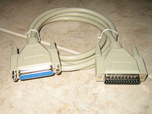
Step 1.
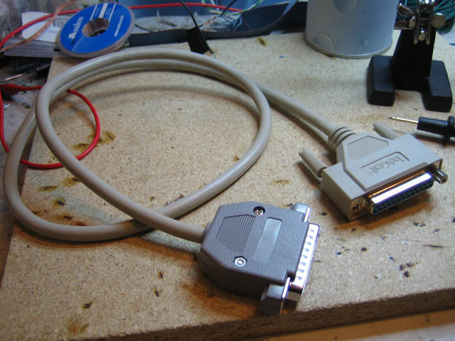
Aquire a parallel extension cable, a nice 6ft would do it.
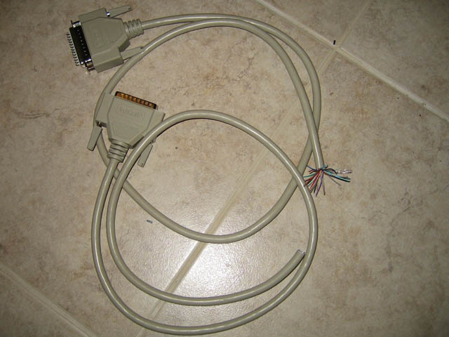
Step 2.
Cut the damn thing in half. We only need a maximum of 3ft (~1meter). We can easily make two cables out of it.
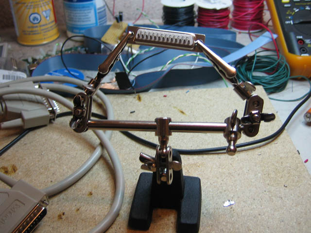
Step 3.
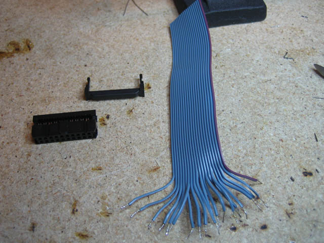
Prepare a new connector opposite gender to the one on the other end of the cable. I like to pre-fill the connector holes with solder at this point to make the connections quickly.
Step 4.
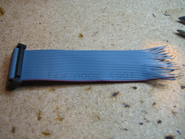
Using a continuity tester quickly map each wire to the proper pin and solder it to the connector.
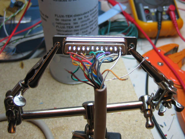
Step 5.
Finish soldering the rest of the wires. Attach a connector housing to make it nice and neat.
Step 6.
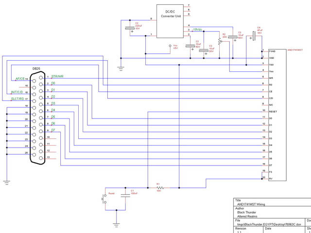
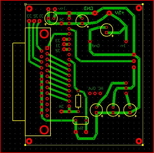
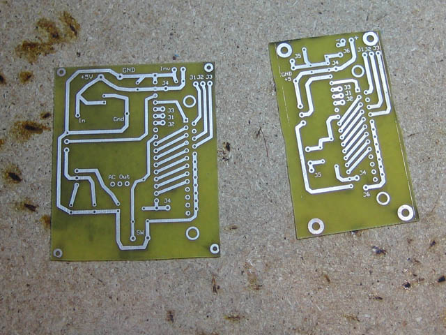
Design your circuit diagram using your favorite CAD software. I used TinyCAD (freeware). Then layout your PCB in your favorite software. In my case ExpressPCB (freeware).
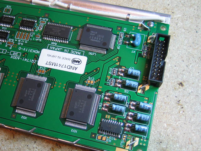
This circuit is for a T6963C driven LCD Display. Incorporating a DC-DC Converter to generate negative voltage signal for driving the contrast control.
Step 7.
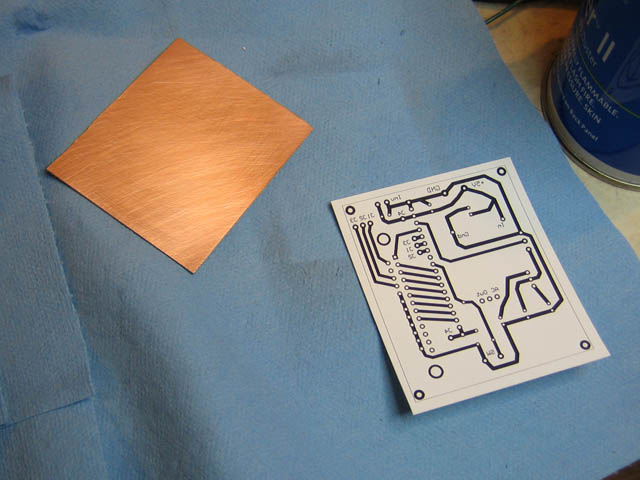
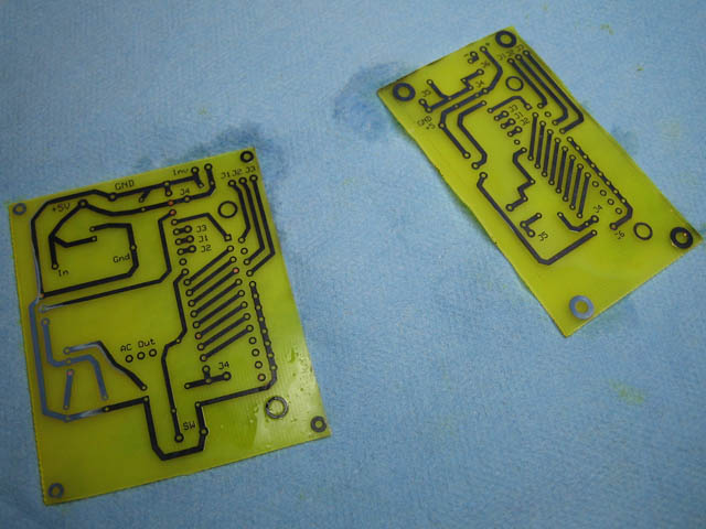
Print out the layout using a Laser Printer on cheapest possible photo paper. Cut out the design, leaving 1/4 inch around. Prepare a copper single sided board. Clean the board with water/soap using a Scotchbrite pad, then follow with acetone.
Step 8.
Place the printed cutout face down on the copper surface and feed it through a laminator. Do this about 3 times to make sure there is a good bond between the photo paper and the copper board
Step 9.
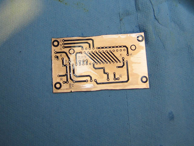
Fill a small container with warm water with soap. Throw the fused board/photo paper into the container for 10-20 minutes. Let it soak enough so that the photo paper comes off the copper board without effort, leaving the toner imprinted on the board.
Step 10.
Dry the board completely and drop it into lukewarm Ferric Chloride solution for about 5 mintues. Agitate to speed up the process. Once all the unwanted copper is removed, dry the board
Step 11.
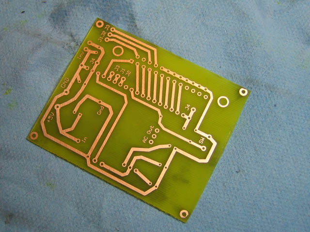
Using acetone remove the toner from the board, exposing the unetched copper underneath.
Step 12.
Submerge the board into Liquid Tin for 5 minutes to tin the traces and prevent oxidation.
Step 13.
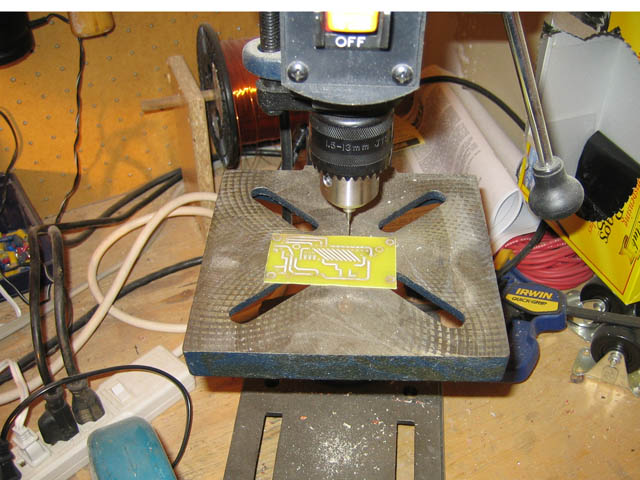
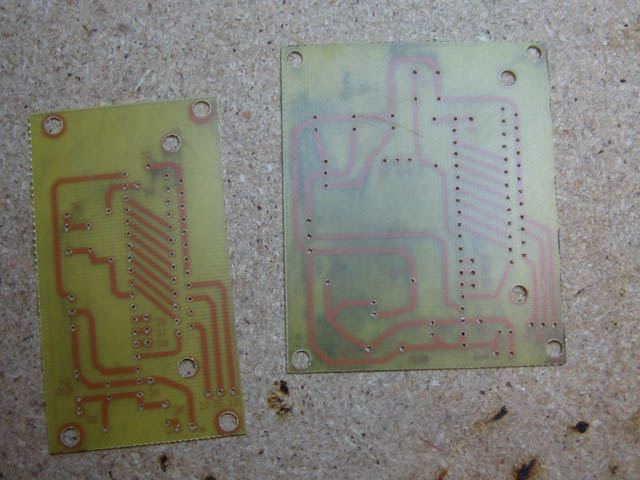
Using #66 and #69 carbide drill bits, drill the component and jumper/wire holes.
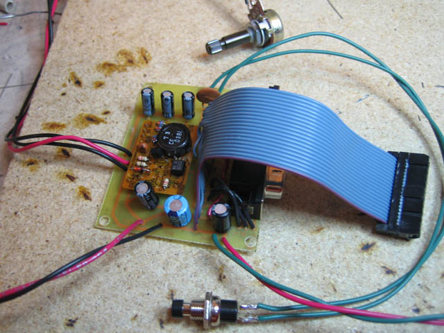
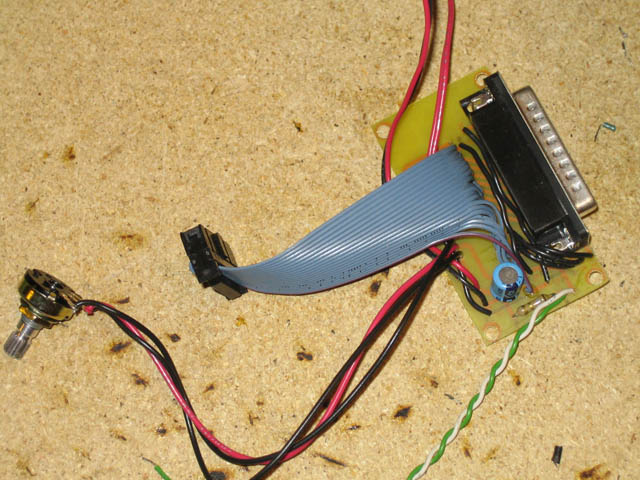
Step 14.
Prepare the ribbon cable that will connect the PCBoard to the LCD. Cut a short length of 20 wire ribbon cable. Crimp on a connector and a strain relief. Split, strip and tin the other end.
Step 15.
Start soldering components to the board, using the original circuit diagram as a roadmap.
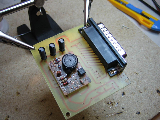
Step 16.
Once all the components have been soldered on. Connect the power supply without connecting the LCD or Parallel port. Check all the voltages are correct. Make sure nothing blows up.
Step 17.
Solder a 20 pin header on the the LCD. Make sure Pin 1 is in the correct direction.
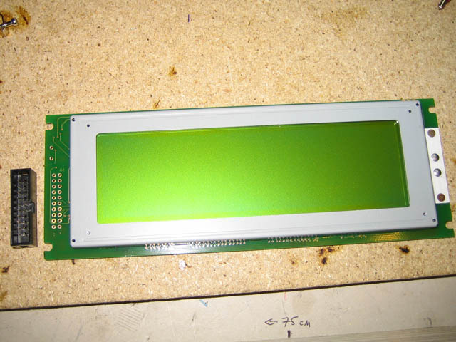
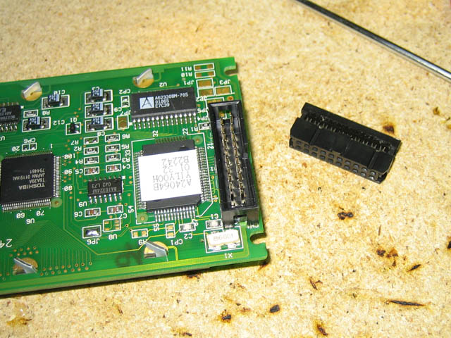
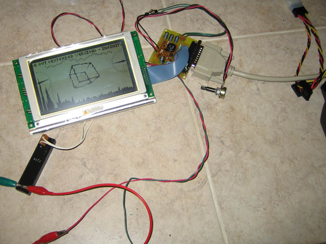
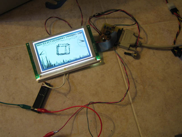
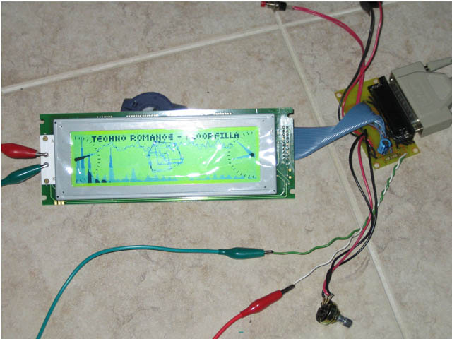
Step 18.
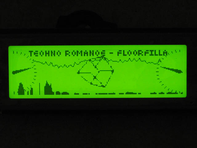
Connect it all and let LCD Studio rip!