I built few more RC flasher boards. Few for friends and one more for another truck of mine. Same design as original but slightly different Arduino code.
Month: February 2014
RGB Fan Mod
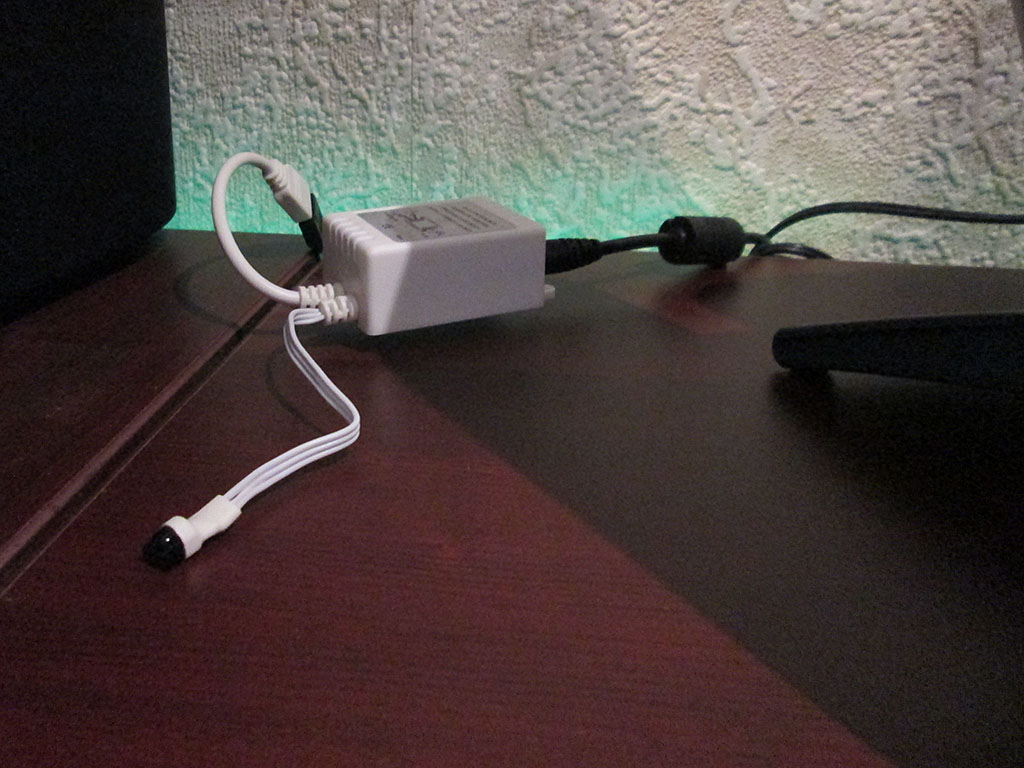
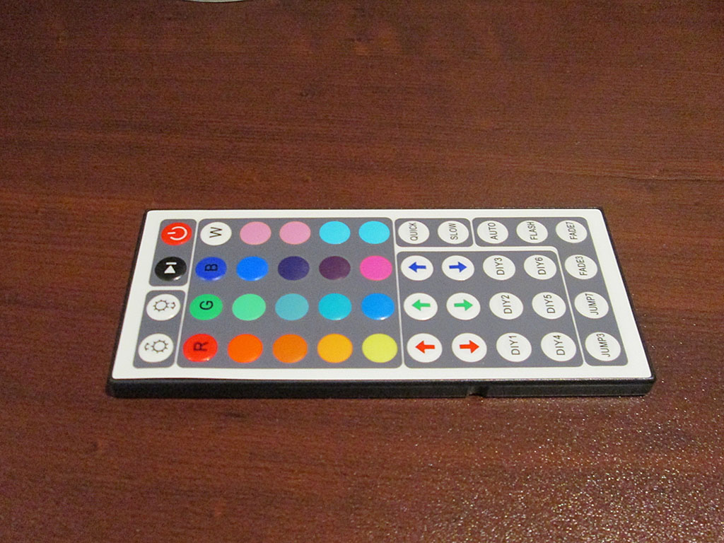
Few months ago I used some RGB LED lighting in my room (eBay China special). The setup uses an IR remote control and a control box to control the lighting. Power is supplied via a high current 12V power supply (10A supply)
My “gaming” computer uses green LED fans which looks kind of odd when using any other color on the strip. Changing the color of the computer required swapping the fans for a different color.
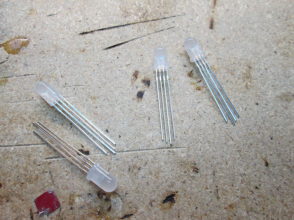
So, I decided to modify the fans to sync the colors of the fans with the rest of lighting. I already had tons of RGB LED’s, so it was really a matter of A LOT of soldering. One thing to note is that the LED ligthing system uses common Anode configuration, with a single 12V rail and 3 (RGB) grounds.
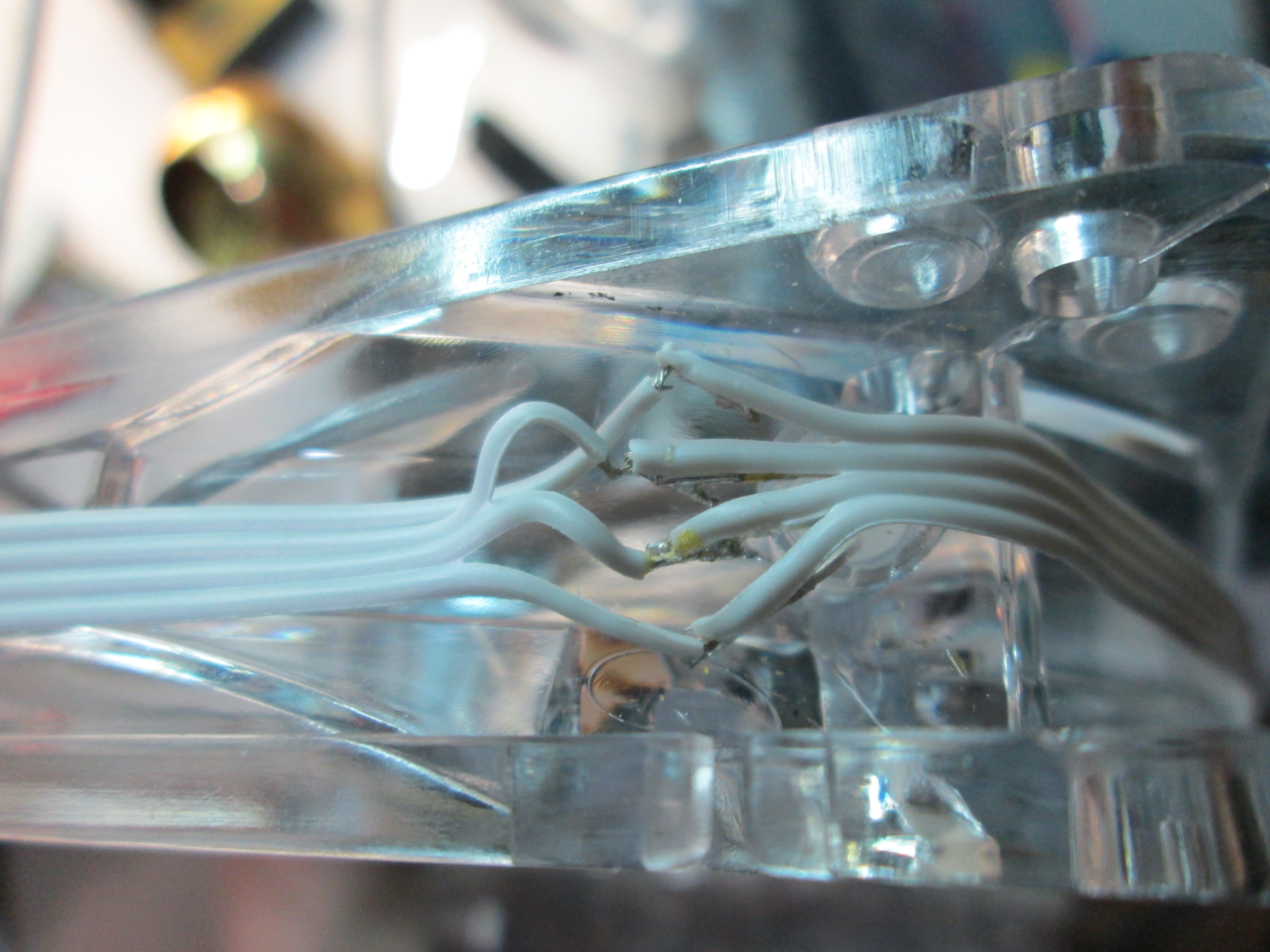
Once I pulled the fans from the computer, I had to remove the old green LEDs from the fan.
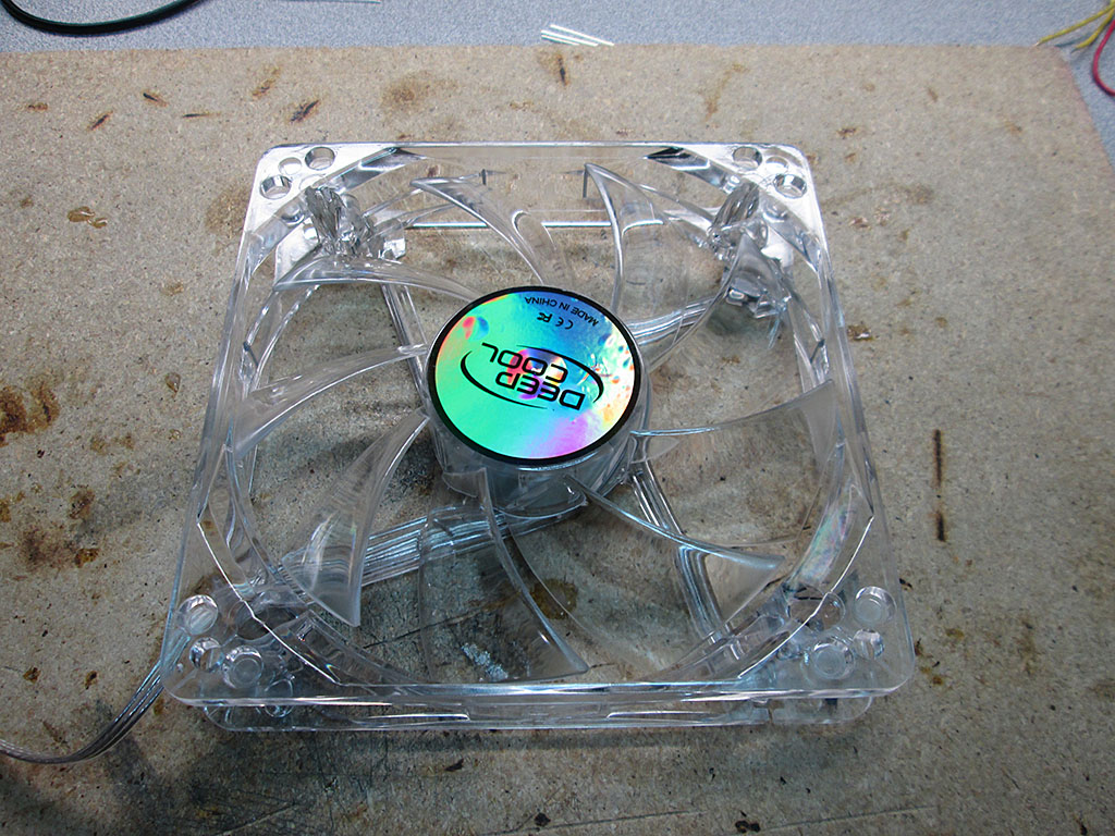
Fortunately the LEDs are simply pressed into place and not glued. This makes them easy to pop out with just a little bit of force.

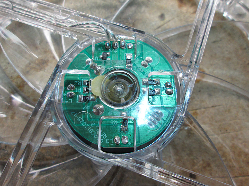
The leads for the fans are connected to a small circuit board underneath the sticker on the fan
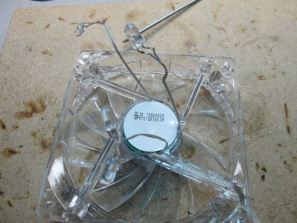
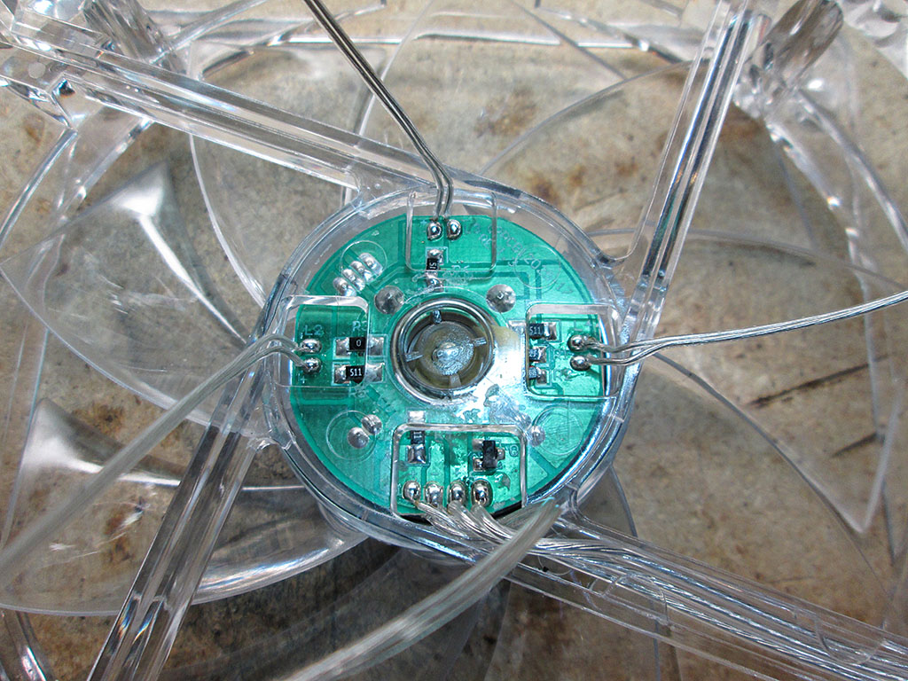
A quick application of a soldering iron and all the LED leads have been removed. Since the LEDs are no longer supplied with fan voltage rail, the brightness of the LEDs will no longer be tied to the speed of the fans.
The RGB leds a just tiny bit larger than the original LEDs so it took a bit of extra force to press them into the socket.
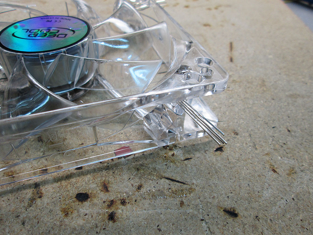
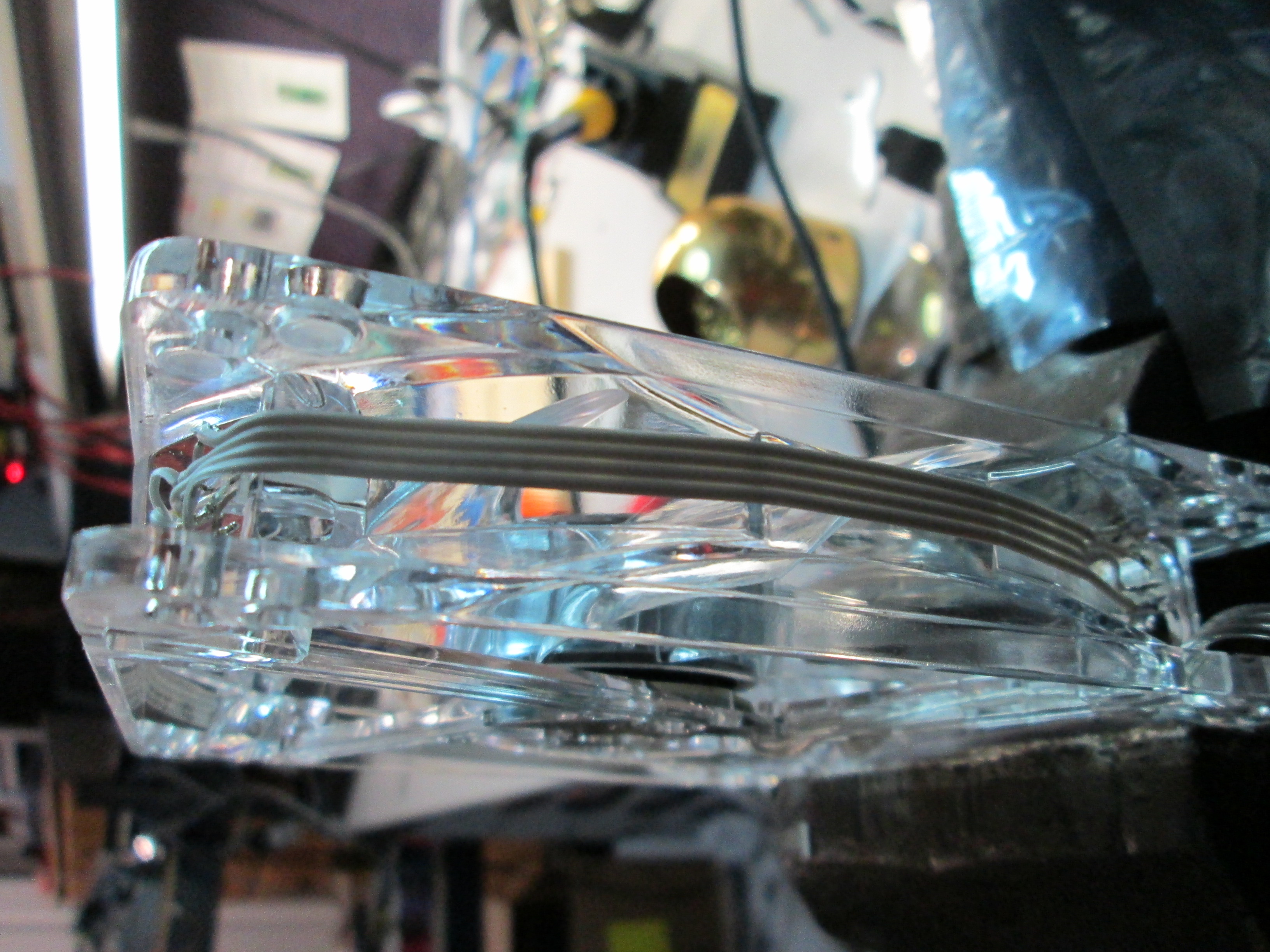
I used standard ribbon cable to carry the RGB voltages across the LEDs in the fan. The individual current for each fan is very low so the ribbon cable can easily handle the load.
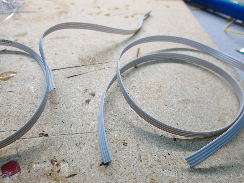
All LEDs were connected via point-to-point connections. This was actually a fair bit of work. The ribbon cable is quite delicate so I had to take extra care when stripping the wire ends as not to cut the lead.

The ribbon cable is nice and flat so it doesn’t affect the overall diameter of the fan much. Still, there would be certain configuration where the fans are too close to an edge where this would be problematic. Fortunately in my case, the fans are spaced sufficiently apart that the ribbon cable doesn’t interfere.
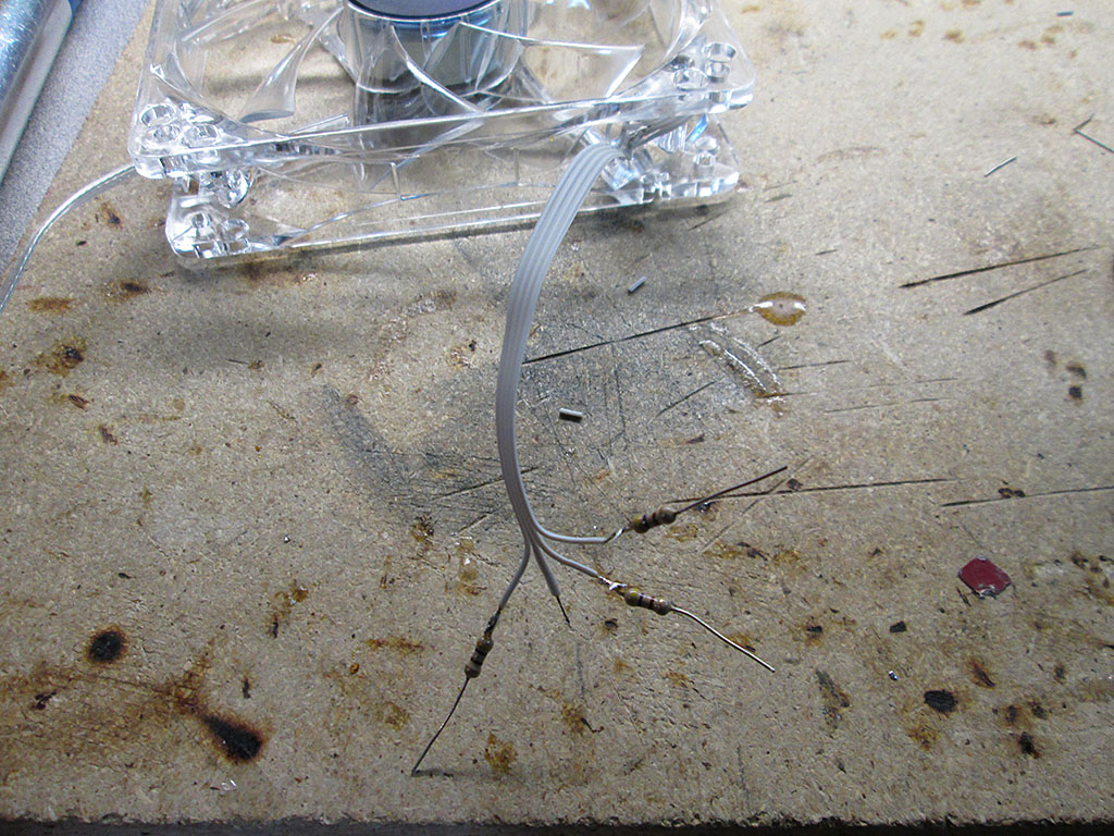
Once all the LEDs were electrically connected they had to be terminated via current limiting resistors. During bench testing I found that the 470ohm resistors provided the best brightness to current ratio at 12V. Since the LED receives power on a common Anode and each color draws slightly different amount of current, it’s important to place the resistors on the individual color leads. Putting the resistor on the anode pin will not work properly when using more than one color at a time.
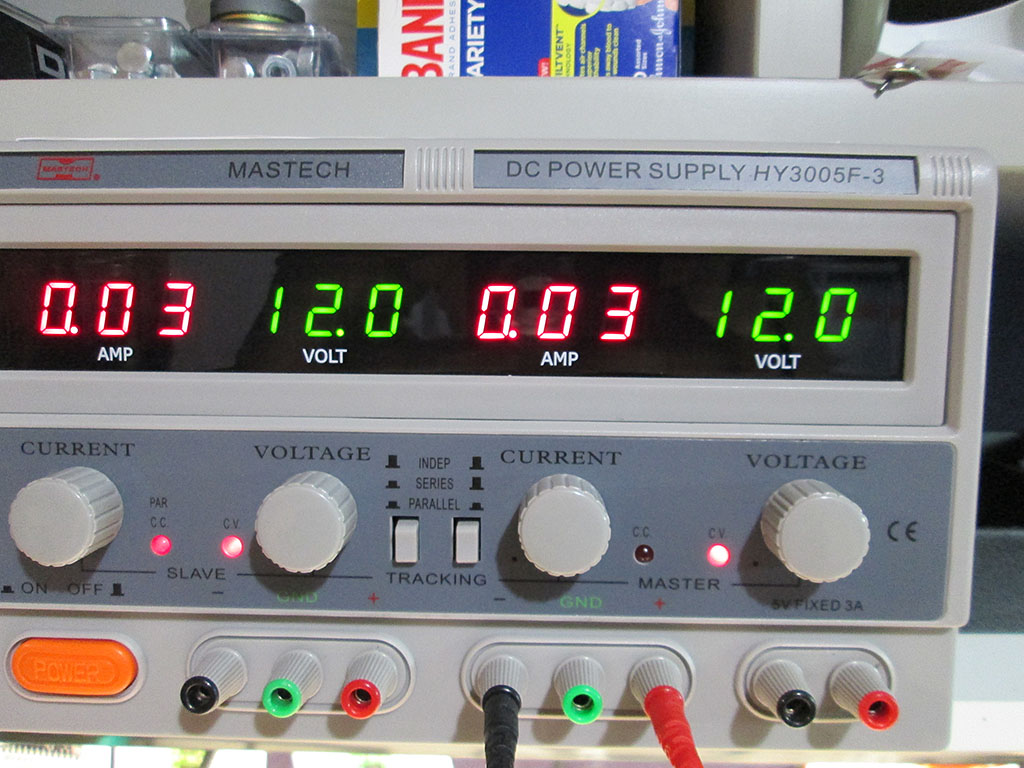
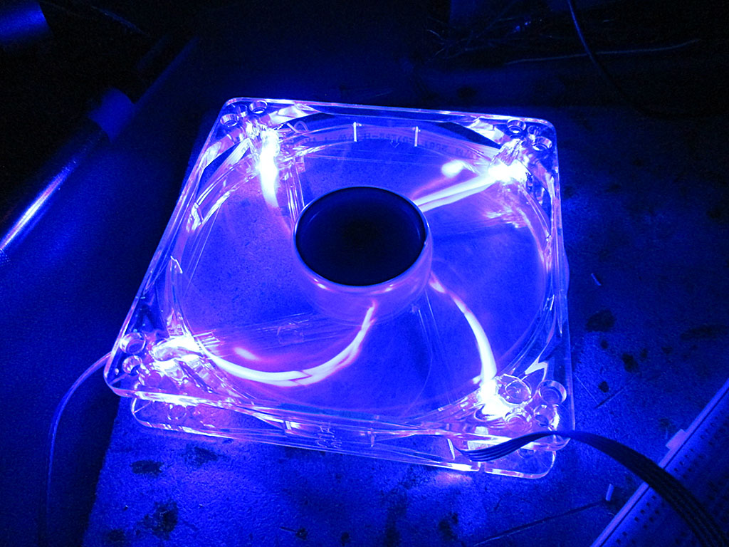
With the first fan completed I did some testing to see how the setup will stack up. I wasn’t sure if the RGB LEDs will be bright enough.
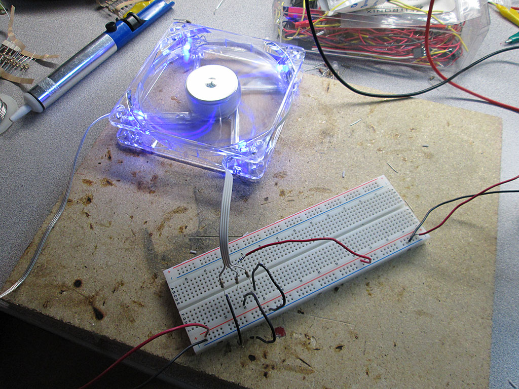
At 12V the individual colors only draw about 30mA per fan.
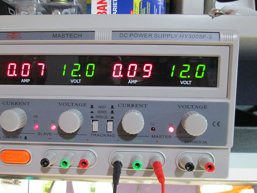
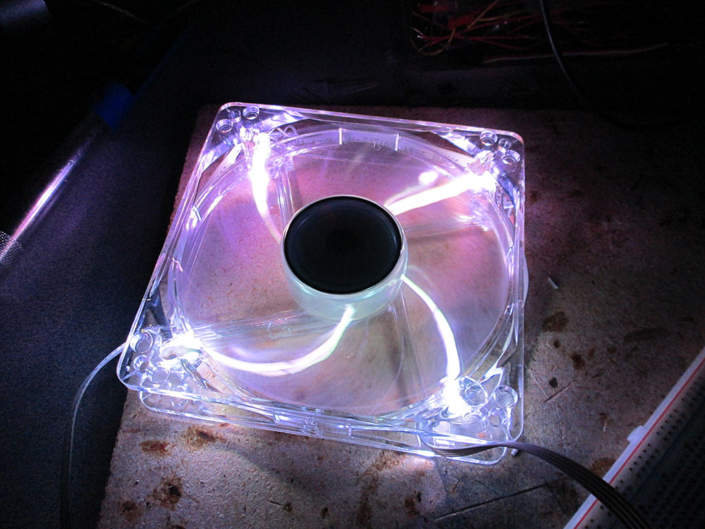
With all the colors lit, the draw was just 90mA. Which works out to under 500mA for the whole computer. A negligible load on the control box for the ambient lighting.
To connect the fans to the LED strip I bought some JST 4 pin connectors. It’s surprisingly difficult to find small 4 pin connectors locally, so I had to do another China eBay order and wait another month for them to show up.
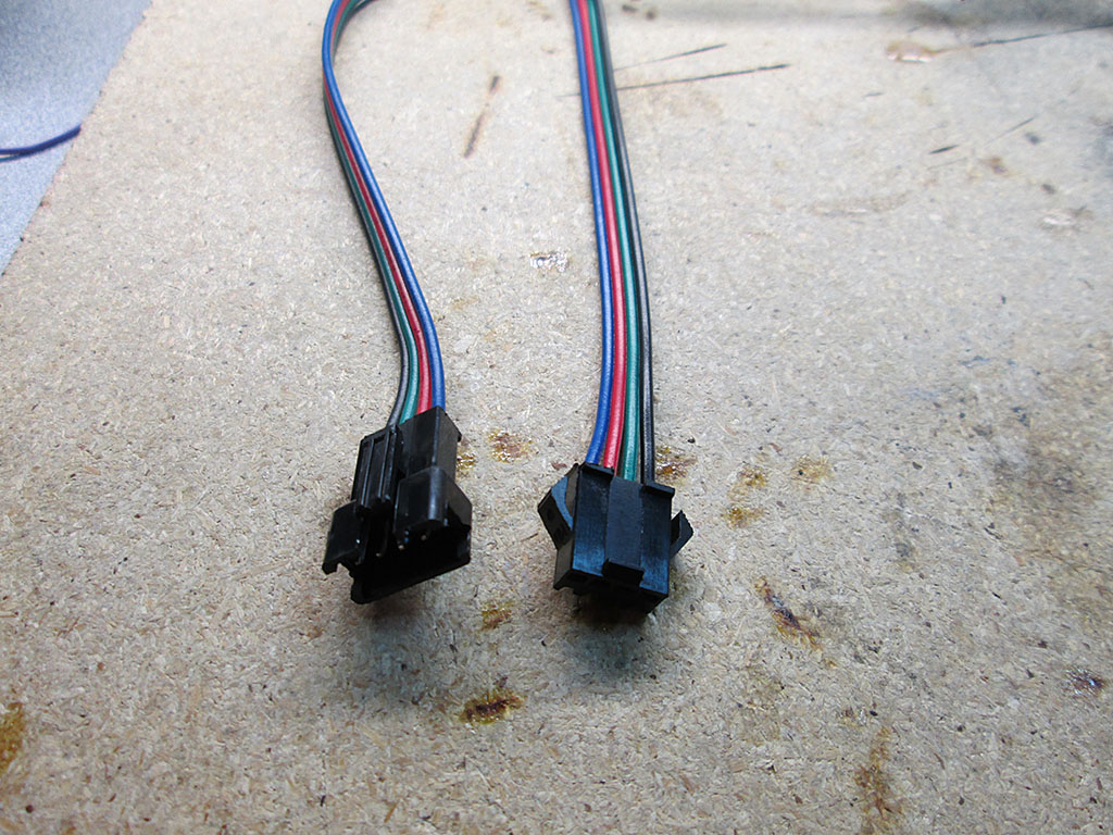
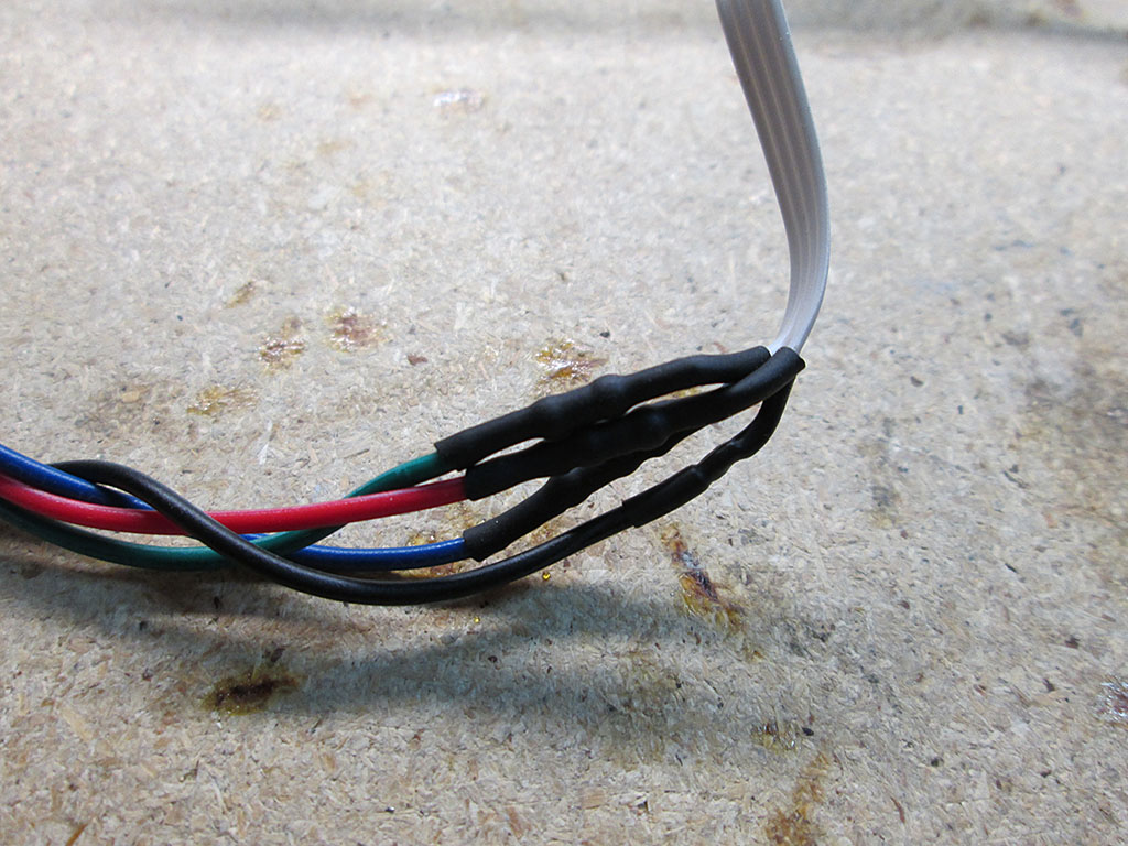
To complete the connection, all the resistors were then wrapped via heatshrink and soldered to the connectors. I gave each fan about 8″ of wire to make the connections between the fans easy.
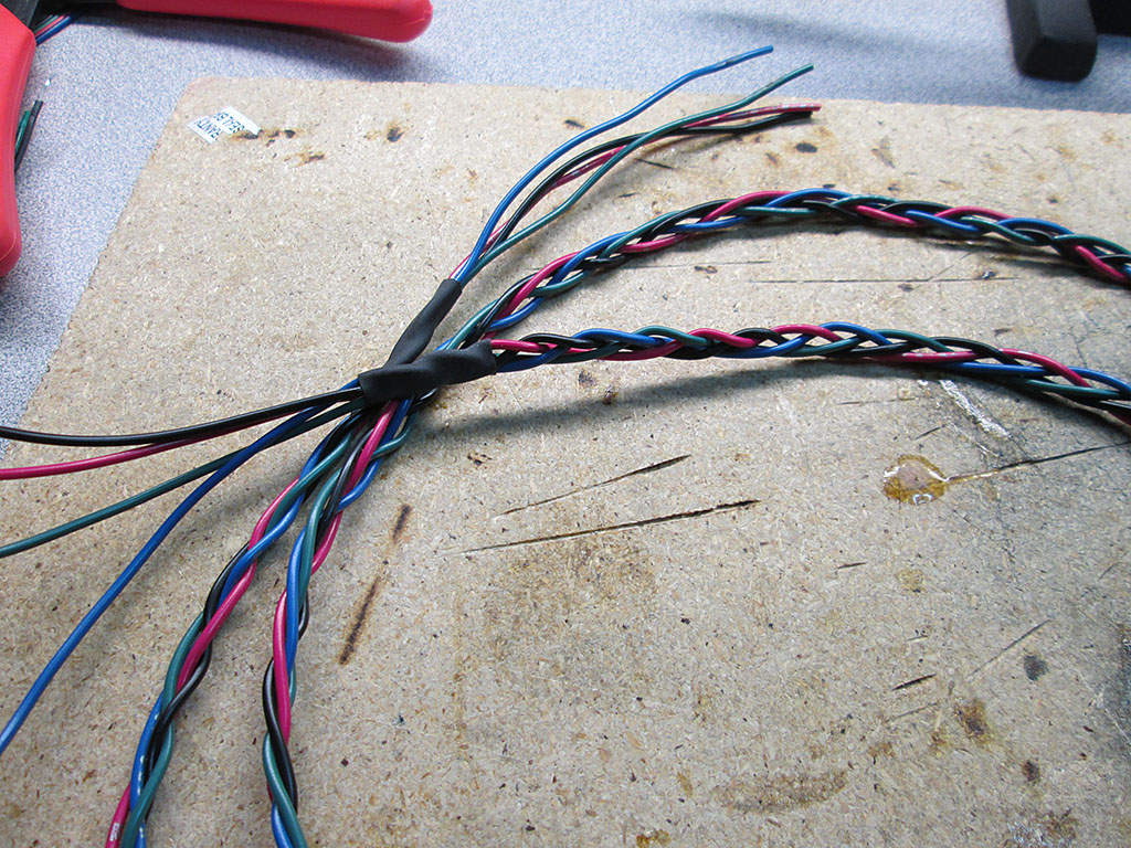
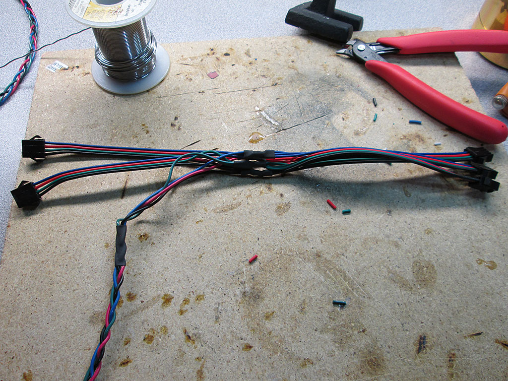
To connect all the fans together and to connect them to the LED strip I braided few 24 gauge wires to make a nice flat cable. This cable will run outside of the computer via a hole (meant for water cooling hose) in the computer case.
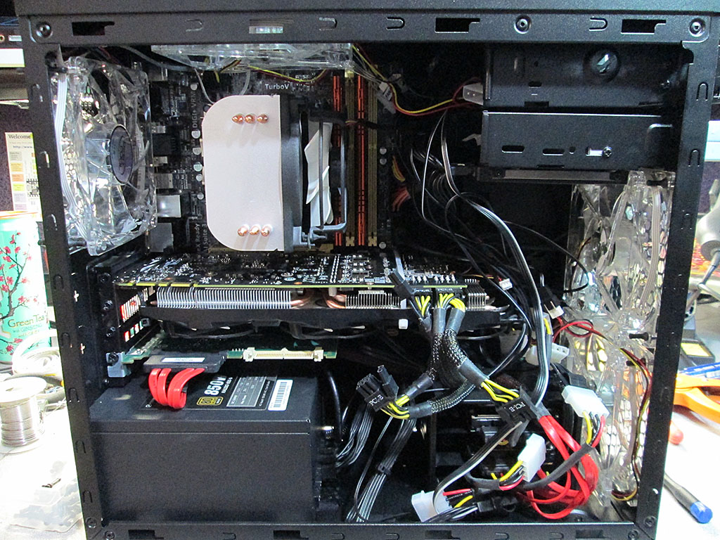
Once all the fans were soldered up, I installed them back into the computer. My wire organization skills are certainly not the best, but then again this is just a Mini ATX case so not heck a lot of room to stash the cabling.
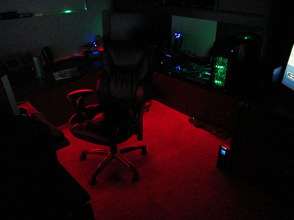
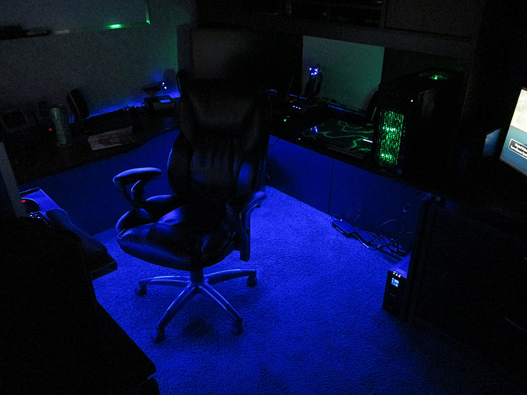
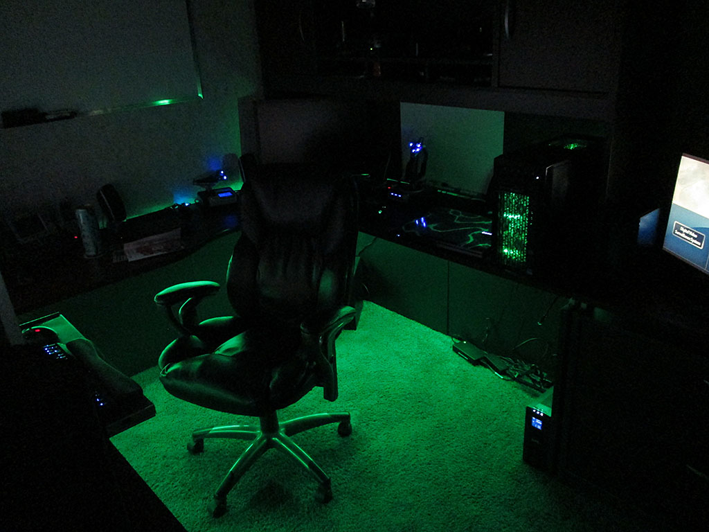
Last step was to connect the supply cable to the LED strip and turn it all on.
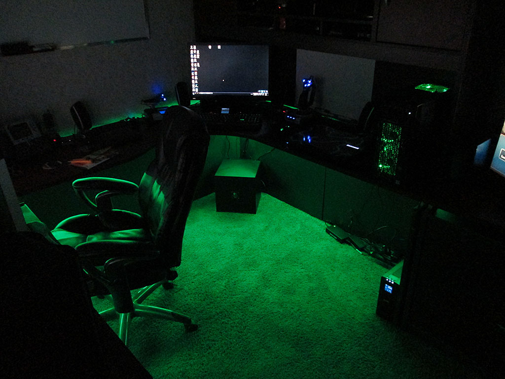
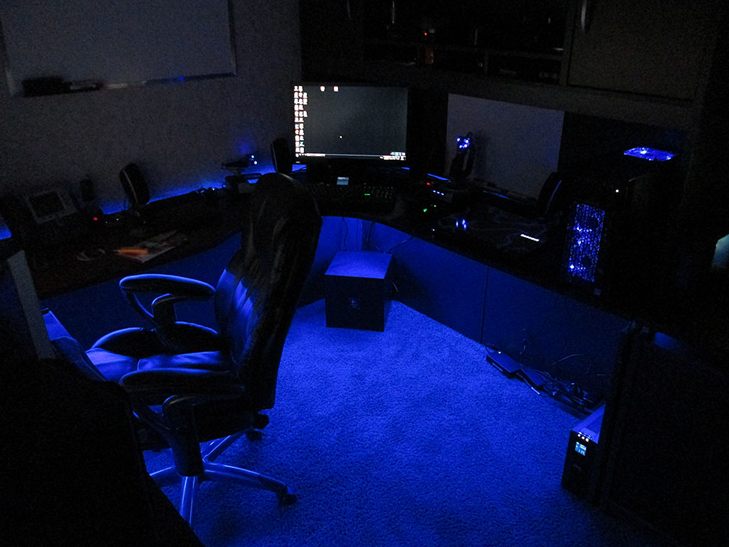
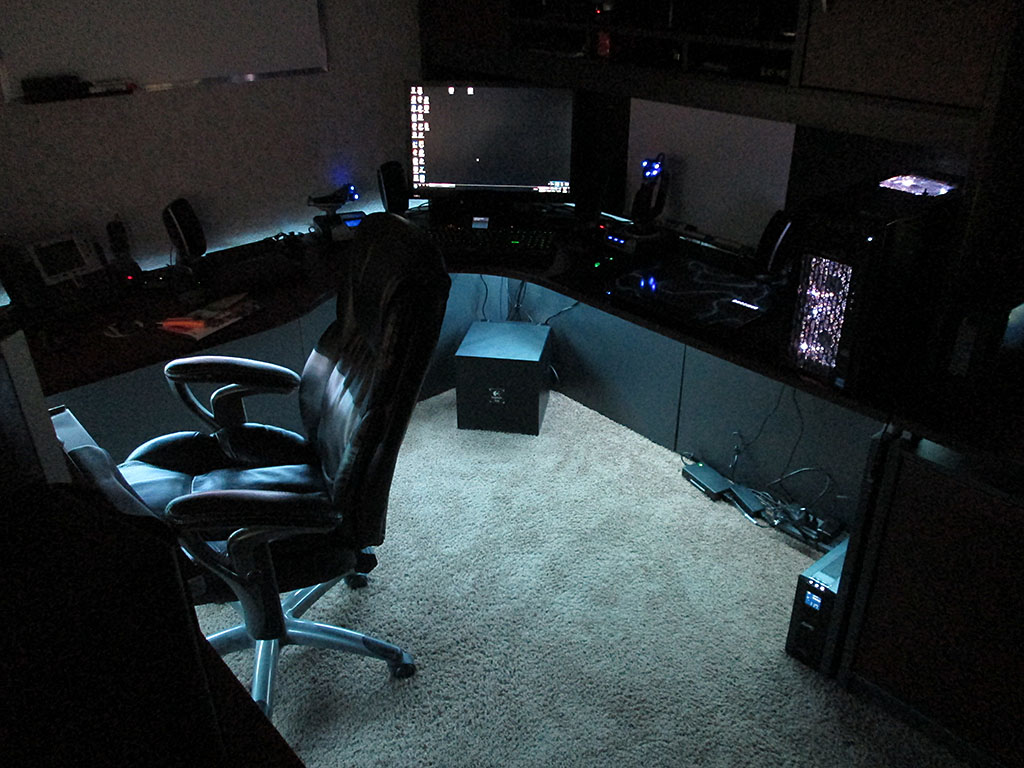
Here’s a short video of the LED system, with the light mode set to cycle all colors.
VOIP at Home

As part of a side project I jumped into the “exciting” world of VOIP and Telephony. Of course, as soon as someone mentioned VOIP or PBX I think Asterisk. Now, I’ve heard of Asterisk for years, and I’ve always considered setting up a PBX at home but I could never figure out how I would utilize the features on a day to day basis. Now that that side project has come up, it was the perfect excuse.
First thing first, I jumped on Kijiji and picked up a set of Cisco 7960G phones.
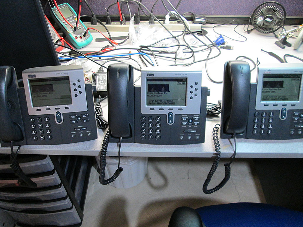
The phones were in decent condition and already have been preloaded with the SIP version of the firmware. They were however each running different version of the firmware so first step was to factory reset these phones and update to latest available SIP firmware.
To factory reset the phone.
* Plug in the phone
* Hold # key until message …
* Press the following key sequence 123456789*0#
* Press 2 to delete network config
* wait for the phone to reboot
Updating firmware is pretty trivial. Once a TFTP server has been configured, simply drop the updated firmware onto the TFTP server and point the phones at the IP address. These phones automatically check for updated firmware on the server during the bootup process.
If DHCP option for TFTP isn’t configured, an Alternate TFTP server can be configured on the phone via Network Configuration. Before attempting to change the setting the phone must be unlocked via option 9. The default password for the phones: cisco
When the phone boots up it checks the TFTP server for configuration files. The two most important files are SIPDefault.cnf and SIP<mac>.cnf. These are two of the files that the phone will look for during start up to self-configure.
The SIPDefault is a great place to put common settings for all phones.
Example Format for SIPDefault.cnf
image_version: P0S3-8-12-00
proxy1_address: "voip.olympia.local"            ; Can be dotted IP or FQDN
proxy2_address: ""              ; Can be dotted IP or FQDN
proxy3_address: ""              ; Can be dotted IP or FQDN
proxy4_address: ""              ; Can be dotted IP or FQDN
proxy5_address: ""              ; Can be dotted IP or FQDN
proxy6_address: ""              ; Can be dotted IP or FQDN
proxy_register: 1
messages_uri:   "*97"
phone_password: "cisco" ; Limited to 31 characters (Default - cisco)
sntp_mode: unicast
sntp_server: "pool.ntp.org"
time_zone: "EST" ; assuming you're in GMT
time_format_24hr: 0 ; to show the time in 24hour format
date_format: "D/M/Y"  ; format you would like the date in
dial_template: dialplan
autocomplete: 0
call_hold_ringback: 1
#nat_received_processing: 0
logo_url: "http://voip.olympia.local/cisco/logo.bmp"
services_url: "http://voip.olympia.local/cisco/services.php"
directory_url: "http://voip.olympia.local/cisco/directory.xml"
SIP<mac>.cnf (SIP<MAC>.cnf replaced with actual MAC address of the phone)
#office phone

image_version: P0S3-8-12-00

line1_name: 100
line1_authname: "100"
line1_shortname: "Ext 100" ; displayed on the phones softkey
line1_password: "secret" ; replace with a strong password
line1_displayname: "THC Inc 100"; the caller id

proxy1_port: 5060
proxy1_address: voip.olympia.local

# Line 2 Setup
line2_name: 1000
line2_authname: "1000"
line2_shortname: "Intercom"
line2_password: "secret"
line2_displayname: "Intercom";

phone_label: "THC Inc.  " ; add a space at the end, looks neater

#remote access to the phone
telnet_level: 2
phone_password: "cisco" ; Limited to 31 characters (Default - cisco)

# uncomment below to connect over the internet
#nat_enable: 1

#custom phone logo
#logo_url: "http://kermit/asterisk-tux.bmp"

user_info: none
Couple of great resources for Cisco config file:
http://wiki.siftah.com/Cisco_7960G_IP_Phone_on_Asterisk
http://www.jtech.net/ip_phone/cisco/7940_sip_config.aspx
There are two providers I’ve signed up with. VOIP.ms and CallCentric.com. Both provide support for SIP/IAX2 phones and have very low rates, which is great for someone who doesn’t use land lines all that often. Having two providers also adds failover for outgoing calls.
I’ve always known about Asterisk but I also found few derived projects like AsteriskNow (turn key distro) and Elastix which had a much more polished web GUI. There’s tons of articles on the web about configuring Asterisk/Elastix and it, in itself is pretty trivial. But there are quite a few gotchas, especially if the server is hosted and open to the internet. For this exercise I ended up with Elastix as it seemed more user friendly than AsteriskNow with the default FreePBX UI.
So, couple of items when configuring a web open Asterisk server.
* Make sure extension passwords are VERY strong.
Since the password is never entered manually (only in Asterisk config and TFTP file config). It can be made impossibly strong and long.
* Protect the server via fail2ban.
Fail2ban is a fantastic solution to brute force attacks. It simply scans the log file file for failed authorization attempts and then simply blocks the incoming connection at the firewall effectively shutting the remote address out. This makes brute-force attacks impractical since the attacker can only try 4-5 passwords / hour for every IP they have.
Elastix already comes with fail2ban pre-installed, just needs to be configured.
/etc/asterisk/logger.conf
[general]
dateformat=%F %T

messages => security
This will create a new log file /var/log/asterisk/message
Add the following to /etc/fail2ban/jail.conf
[asterisk-iptables]
# if more than 4 attempts are made within 6 hours, ban for 24 hours
enabled  = true
filter   = asterisk
action   = iptables-allports[name=ASTERISK, protocol=all]
              sendmail[name=ASTERISK, dest=email@domain.com, sender=fail2ban@yourdomain.com]
logpath  = /var/log/asterisk/messages
maxretry = 4
findtime = 21600
bantime = 86400
Create a new file /etc/fail2ban/filter.d./asterisk.conf
 Fail2Ban configuration file
# Author: Xavier Devlamynck

[INCLUDES]

# Read common prefixes. If any customizations available -- read them from
# common.local
before = common.conf

[Definition]

# Option:  failregex
# Notes.:  regex to match the password failures messages in the logfile.
# Values:  TEXT
#
#log_prefix= \[\]\s*(?:NOTICE|SECURITY)%(__pid_re)s:?(?:\[\S+\d*\])? \S+:\d*

failregex = SECURITY.* SecurityEvent="FailedACL".*RemoteAddress=".+?/.+?//.+?".*
            SECURITY.* SecurityEvent="InvalidAccountID".*RemoteAddress=".+?/.+?//.+?".*
            SECURITY.* SecurityEvent="ChallengeResponseFailed".*RemoteAddress=".+?/.+?//.+?".*
            SECURITY.* SecurityEvent="InvalidPassword".*RemoteAddress=".+?/.+?//.+?".*

# Option:  ignoreregex
# Notes.:  regex to ignore. If this regex matches, the line is ignored.
# Values:  TEXT
#
ignoreregex =
* Firewall issue (Extension UNREACHABLE)
There’s a potential issue when using extensions that connect to the host PBX via the internet. Specifically, shortly after the extension connects it’ll disconnect and Asterisk will report the extension as UNREACHABLE, even though the ping is less than 2000ms (default for qualify=yes).
Changing the value of qualify to higher numbers (i.e. qualify=6000) has no effect.
The problem is that by default Asterisk sends a keep alive command to the phones once every 60 seconds, a lot of firewalls will close the UDP socket within 60 seconds as part of cleanup. So, to combat this the fix is to change the default “qualifyfreq” on Asterisk to a value less than 60 seconds. I changed the value to 45 seconds and it seemed to fix the problem for me.
The file to modify is located at /etc/asterisk/sip_custom.conf.
Simply add the following lines to the file:
qualify=5000
qualifyfreq=45
keepalive=yes
This will ping all the connected devices every 45 seconds and it’ll wait 5 seconds for response before timing out.
Additionally, in pfSense go to: Firewall -> System -> Advanced -> Firewall/NAT -> Firewall Optimization Options and change the option to “Conservative”. This will increase the timeout for the UDP connections before pfSense considers the connection closed and removes the socket.
* Locking down Web Interface.
If you absolutely must have port 80/443 open to the web, it’s a good idea to move the default web site to a virtual hosted site as it’ll make it a bit harder for bots to discover the site since it can only be accessed via proper url.
* Cisco Phone Logo
The logo image on the 7960G phones can be customized. It is a simple 4 bit image with a size of 90×56 pixels. The phone will automatically rescale larger images but it won’t look very good. I found the best way to save a compatible image is to use MS Paint and save the image as 256 color bitmap. The 7960G will also attempt to dither the image to display different shades.

* Intercom System / Paging
This turned out to be more a challenge than I originally thought. Cisco SIP firmware doesn’t officially support paging so a workaround is to configure a line with auto-answer capability and then create a paging group in Elastix. Even though the 7960G has auto_answer configuration option, this feature can not be enabled via the config file and has to be manually configured on each phone. Not a big deal when dealing with a dozen or so phones, definitely an issue when dealing with large deployments.