My RC Flasher Project is complete. I’ve done a write up of it here.
Author Archives: Tom Heiber
Windows 7 PPTP VPN Local Domain Authentication
Here’s a hidden gem. When connecting to another site domain via Windows PPTP (Yeah I know it’s no longer secure). Windows will lose connectivity to the local domain and might even cause an account lockout as Windows will attempt to use VPN credentials on local domain and will fail authentication often without a prompt.
There’s a hidden setting in the .pbk file that prevents credentials from being overwritten.
The file is located in C:\Users\<USERNAME>\AppData\Roaming\Microsoft\Network\Connections\Pbk
* Open the file in Notepad.
* Change UseRasCredentials=1 to UseRasCredentials=0
* Save file and reconnect VPN
And that’s it. Now even with the gateway being redirected all local authentications will continue to work.
Car Detailing 101
People always ask me about my car and how does it look so clean and shiny. The truth is that car detailing requires A LOT of work and a lot of attention to detail. The car will only shine if the paint is very smooth as it’ll not cause light to scatter in every direction. Black cars are notoriously difficult to keep clean but arguably look best when clean.
The best time to detail a car is either Spring or Fall when the ambient temperature is between 18-24 degrees Celsius and low humidity. This makes is warm enough for the waxes, glazes to dry quickly and not hot enough that the compound dries too quickly when polishing.
The obvious first step is to wash the car. Typically this involves spraying the car down with a hose to remove the mud and dirt from the car. I don’t usually use a pressure washer on the car as the car is almost never dirty enough to warrant it.
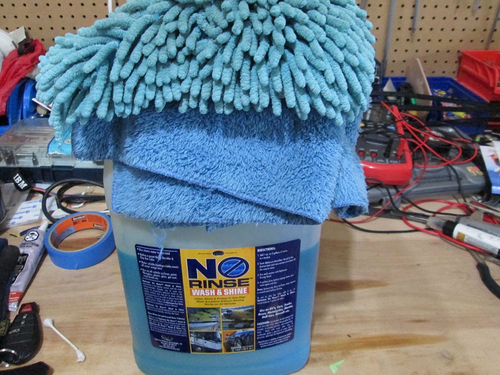
Once the car is sprayed down I use Optimum No-Rinse to wash the car. I found this to be the best way to clean the car. Just add a splash of no-rise to a bucket of warm water. Then simply use a microfiber sponge to clean the car quickly followed by drying using cookie monster sheets. The Cookie Monster sheets are microfiber towels that use very fine, very soft fibers that soak up water extremely well.
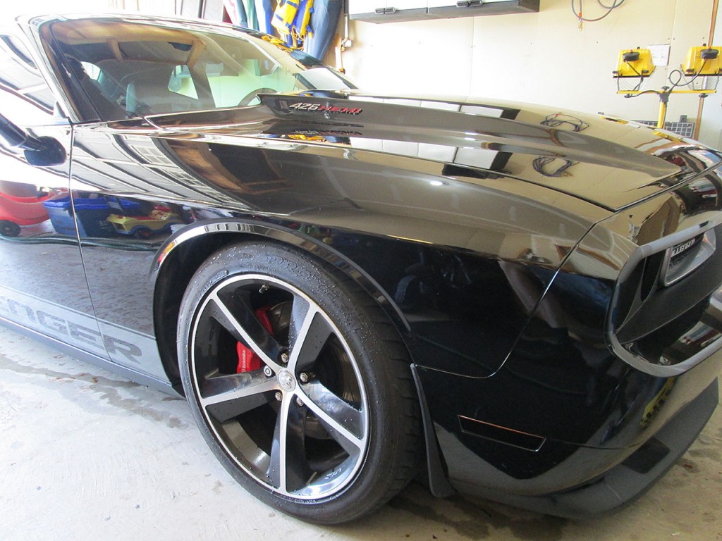
Once the car is clean of dirt it’s time to mask off areas that we don’t want the buffer to score. The polishing compound is brutal on non painted surfaces like plastic or rubber trim. It’ll either scratch the surface or leave behind a white reside that’s quite difficult to remove.
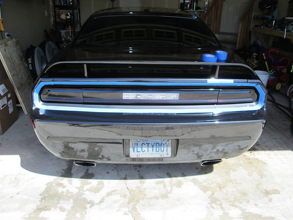
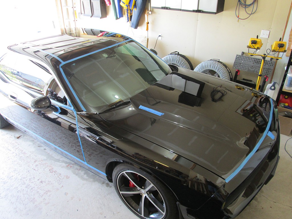
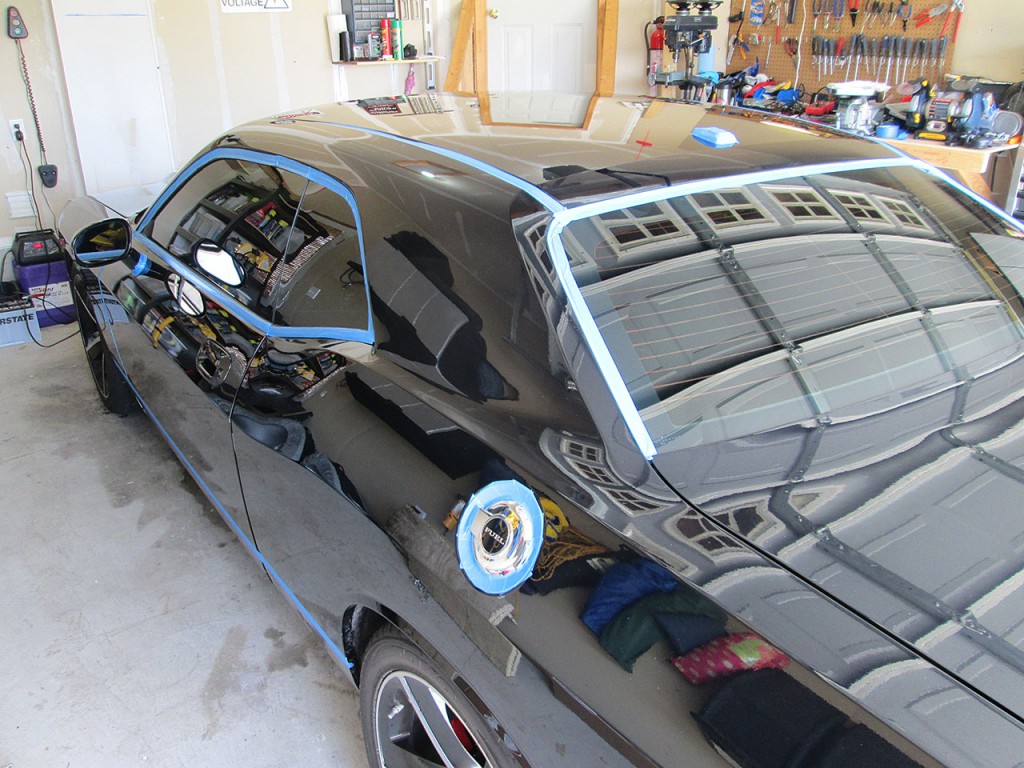
I usually take my time masking the car. This saves a lot of headache later when cleaning up after the polishing stage.
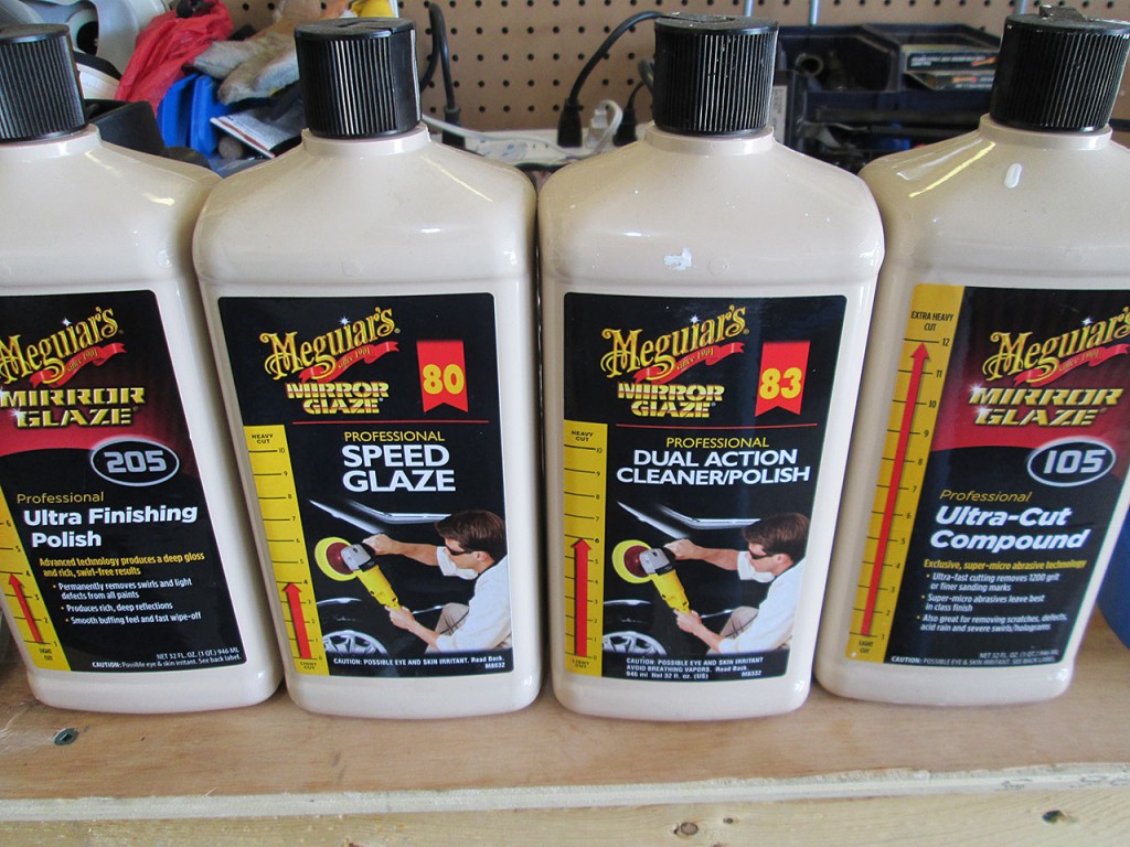
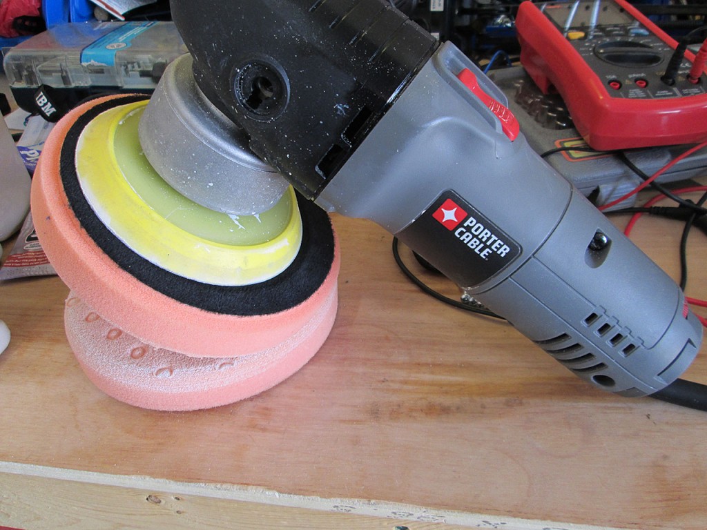
For polishing the car I use a series of Meguiar’s products. Depending on severity of the scratches or swirls I’ll use different one based on it’s cutting strength. For removing swirls and oxidation I usually use cut level 4-6 to preserve as much clear coat as possible. For deeper scratches or heavy swirls I use the Ultra-Cut Compound along with an orange (Mild) cut pad. This combo prevents the clear coat from hazing while still cutting fast enough to remove scratches relatively quickly. For really deep scratches I’ll use a yellow cutting pad. For polishing I use a Porter Cable random orbital polisher with 6.5″ pads. During normal polishing I run the Porter Cable at speed 5 with occasional jump to Speed 6 to force the compound out of the pad.
When I work on the car I always work from top to bottom. So I start with the roof, then work the hood and trunk. Then front quarter panel, doors, rear quarter panel. Then finally the rear and front bumpers.
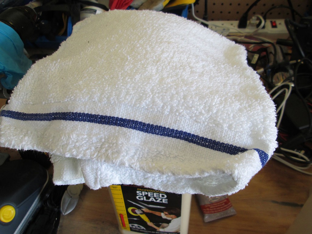
To wipe off the compound and to inspect the paint surface I use regular terry cotton sheets. I go through a lot of cotton towels during the polishing process. Make sure that the towels are clean and if the towel ever hits the ground, toss it. It doesn’t take much for the towel to pick up some dirt and it’s not worth risking scratching the car even more when trying to wipe off the compound.
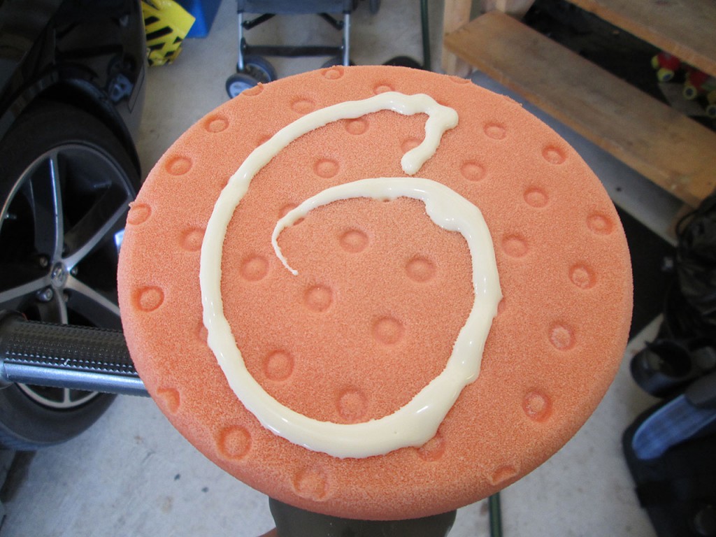
To start polishing I apply a bit of the compound on the pad, then spread it around the work surface with the polisher turned off. This prevents the compound being splattered everywhere when the polisher is turned on. Then simply glide the polisher on the work surface. There is very little pressure required when polishing. All work is done by the compound and the pad. When the compound dries up, simply apply more compound. The dry pad will not do much to remove scratches. When polishing the car, check the temperature of the work surface by touching with the hand. Getting the paint too hot can cause damage to the finish.
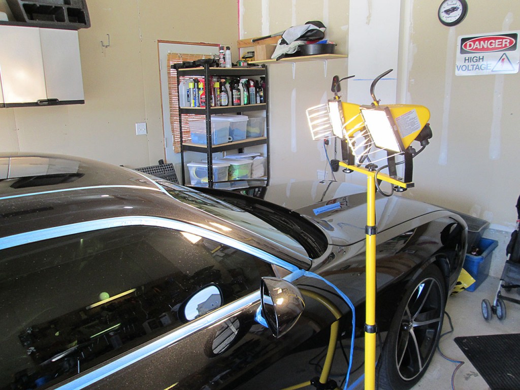
To inspect the work surface I use halogen work lights. These are bright enough to show any imperfections in the paint, though they radiate a lot of heat and are difficult to work with in the summer. These lights will also heat up the paint if working on darker colors which makes it harder to work with.
[14 Hours Later]
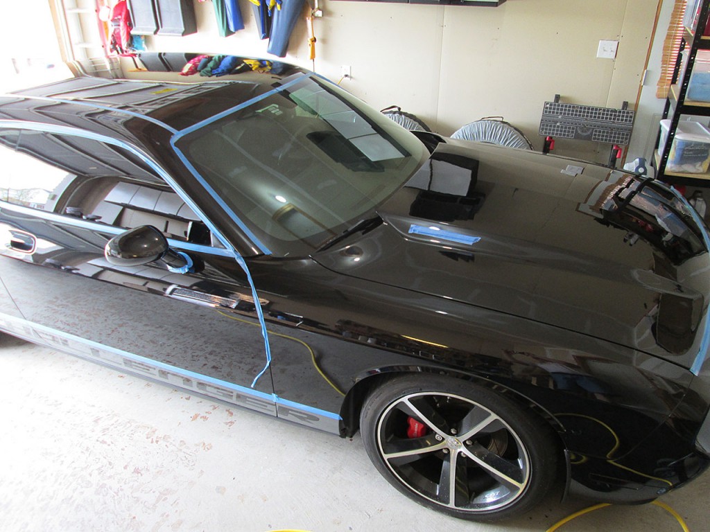
The polishing stage all done. This process took about 3 days as the car hasn’t been detailed at all last year so there were a lot of small scratches to remove. The polishing process leaves a lot of white compound residue behind. I use a combination of compressed air and cotton towels to clean off the compound.
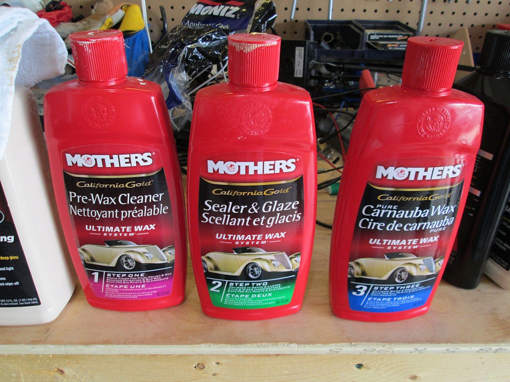
Once the car is polished it’s time to make it stand out. I use the 3 Step system from Mothers. This includes the Pre-Wax cleaner to remove any remaining compound residue, Sealer and Glaze that gives the car the “Wet” look and finally Carnauba Wax to give it that stand-out shine and make the surface of the car slick which prevents dirt from sticking to the car.
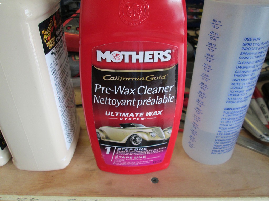
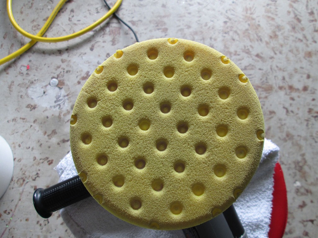
Step 1 is to use the Pre-Wax Cleaner / Polish and Medium Cut Yellow pad to remove any remaining compound residue from the car. This will also removing any previous coat of wax from the car. This process is rather quick as by this time the surface area is already pretty clean and now we’re only interested in removing polishing residue. A quick buff with the Porter Cable and wipe with the cotton towel and we’re ready to apply the Glaze.
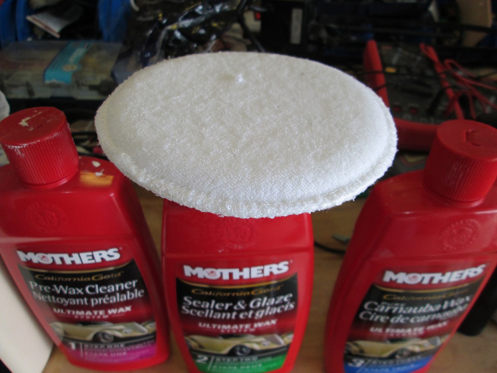
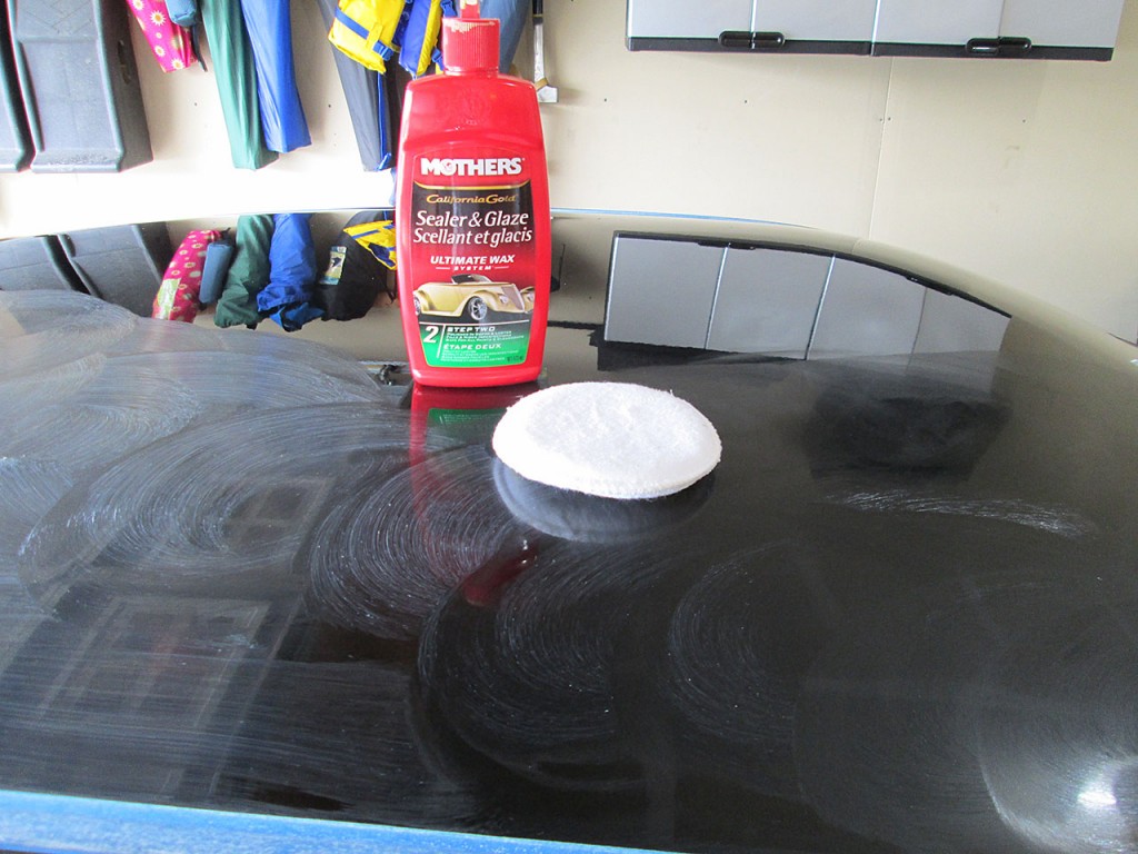
The rest of the process is done entirely by hand. I use small applicator pads to spread the glaze on the paint. Just like polishing, I start with the roof and work my way down.
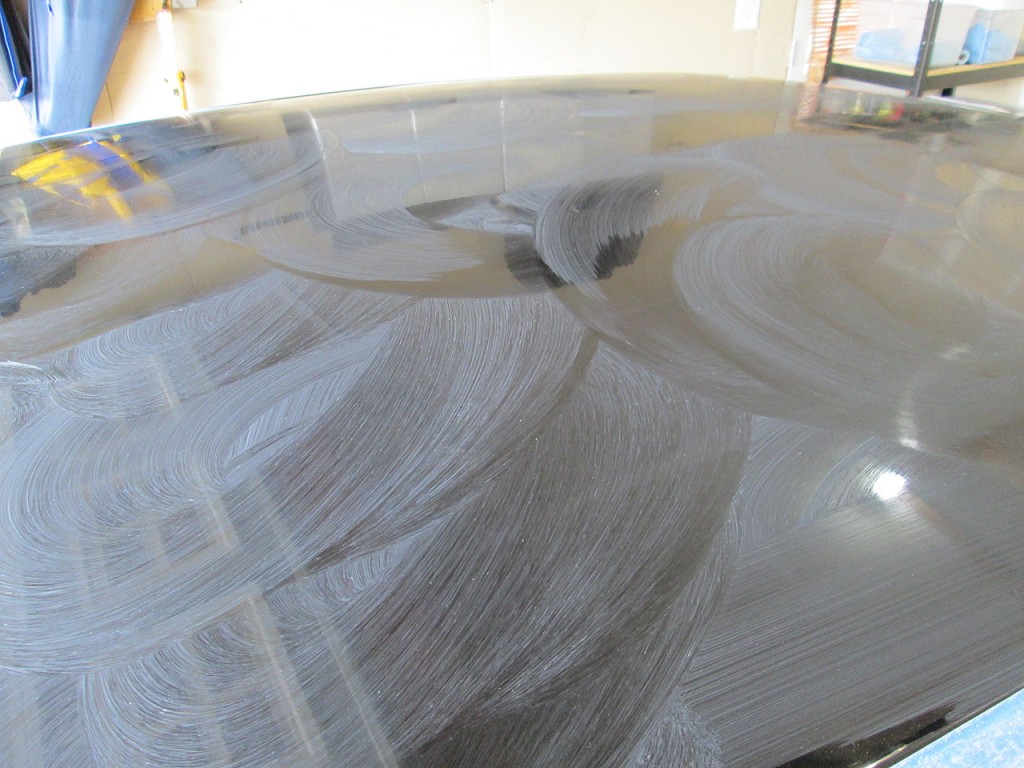
Typically I’ll apply a quick coat, wait about 5 minutes for the glaze to start hazing over and then apply another coat to ensure even coverage. Once the glaze has been applied I wait 20-30 minutes for it to haze over (if it’s cool outside the glaze can take longer). After the glaze has hazed over simply use a clean cotton towel to wipe off the Glaze from the car. This is rather messy as the glaze leaves a fair bit of residue so a lot of buffing is required while constantly turning the towel.
Once the Glaze has been wiped off it’s time to apply the wax.
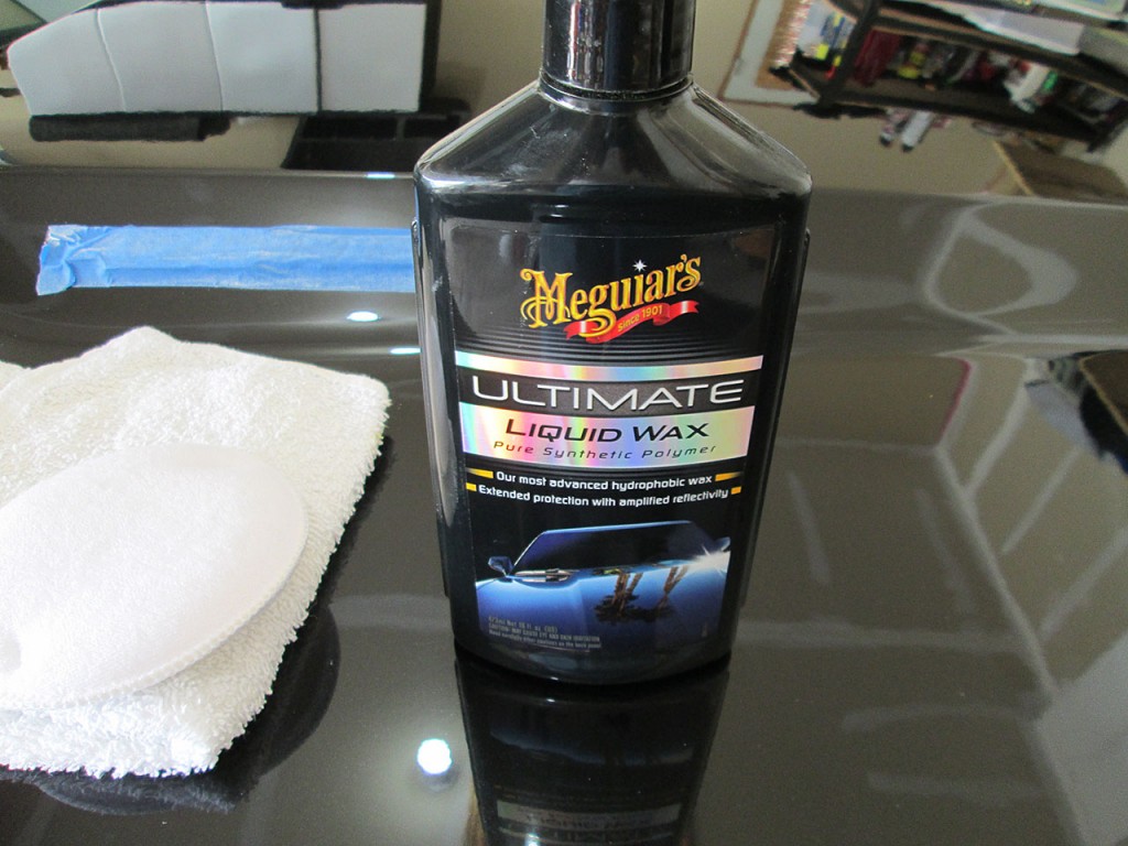
I have lately switched to synthetic wax from the natural Carnauba wax. But because I still have a lot of Carnauba wax left I use the Synthetic wax on surfaces that are exposed to sun the most (roof, trunk, hood) and most exposed to elements (front and rear bumpers). The rest of surfaces (quarter panels and doors) I use Carnauba wax.
Once the remaining Carnauba wax is gone I’ll use the Synthetic wax exclusively. There are many advantages to synthetic wax. Biggest advantages being that it doesn’t leave any residue behind, it lasts a lot longer than Carnauba wax (which melts in the hot sun) and unlike natural Wax it’s safe to use on plastic trim as it’ll not stain it. Carnauba wax is notoriously difficult to remove from porous plastic trim so masking is incredibly important where synthetic wax simply wipes off. The big difference in application is that synthetic wax requires microfiber cloth to wipe off instead of cotton cloth that natural wax uses. Using cotton cloth on synthetic wax will leave a lot of streaks that are next to impossible to remove.
Some argue that the synthetic wax doesn’t quite leave the car looking as good as natural wax but personally I do not see much difference between Synthetic and Carnauba wax.
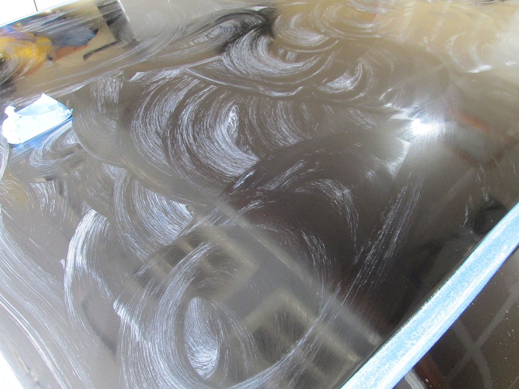
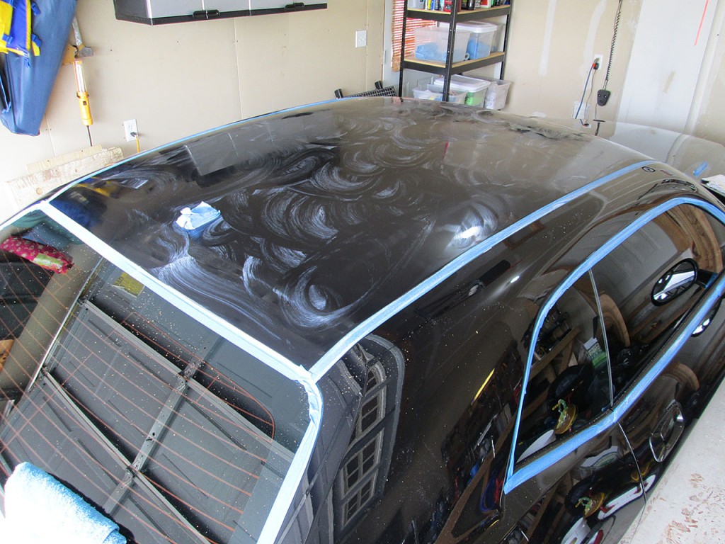
The process of applying wax is exactly the same as applying Glaze. Using application pad simply spread the wax on to the paint surface. Typically using multiple thin coats gives better results than a single thin coat. Additionally, by this time the applicator pad will glide over the paint much easier than when applying the glaze as by now the pad is already gliding on the glazed paint.
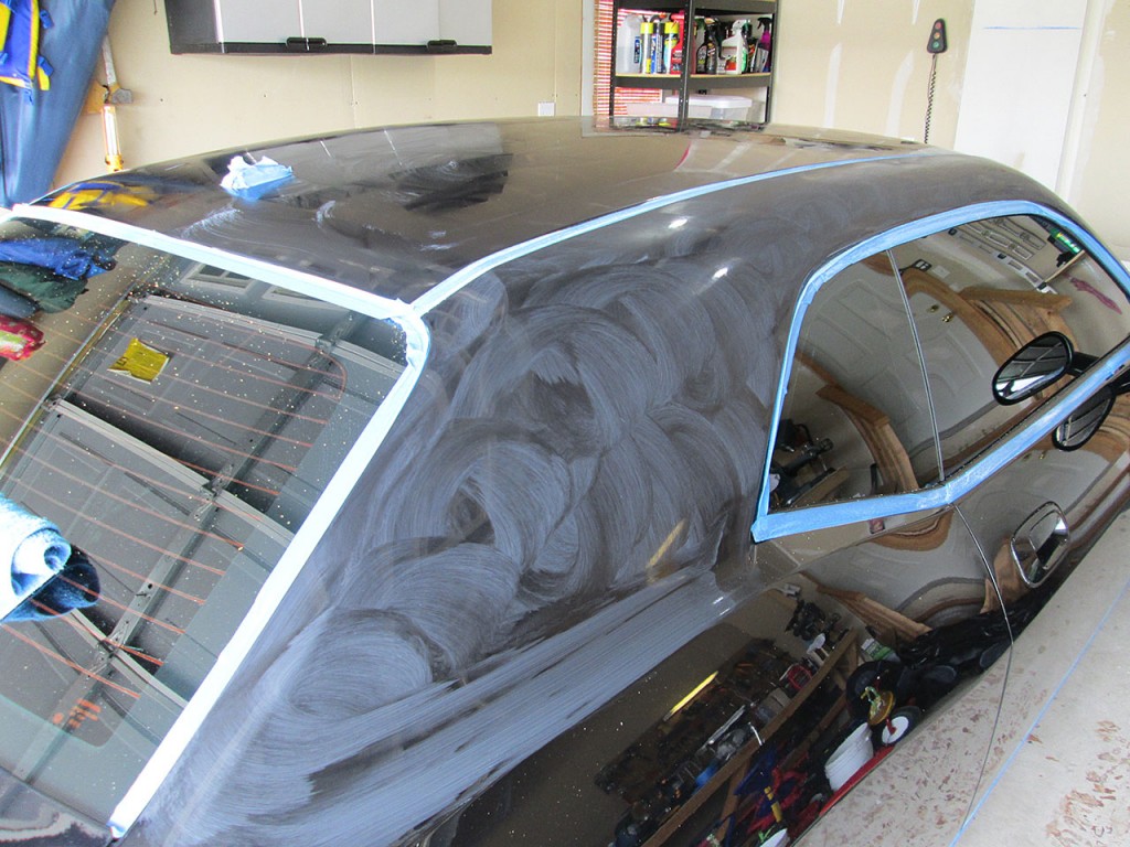
By this time when waxing/glazing the car I break the process into multiple stages. Meaning that by the time the wax is drying on the roof, I’m already applying the glaze to the next surface and paint polish the following one. This makes the process much quicker and I can finish polishing, glazing and waxing the whole car in just a day.
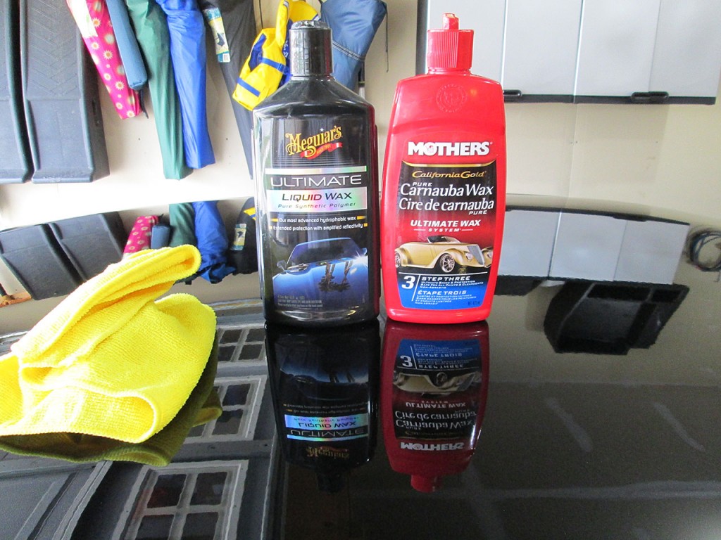
Once the wax has dried simply wipe it off to reveal an extremely glossy, reflective surface. It’s easy to know when remaining residue is gone when the towel glides very easily over the paint surface with absolutely no resistance.
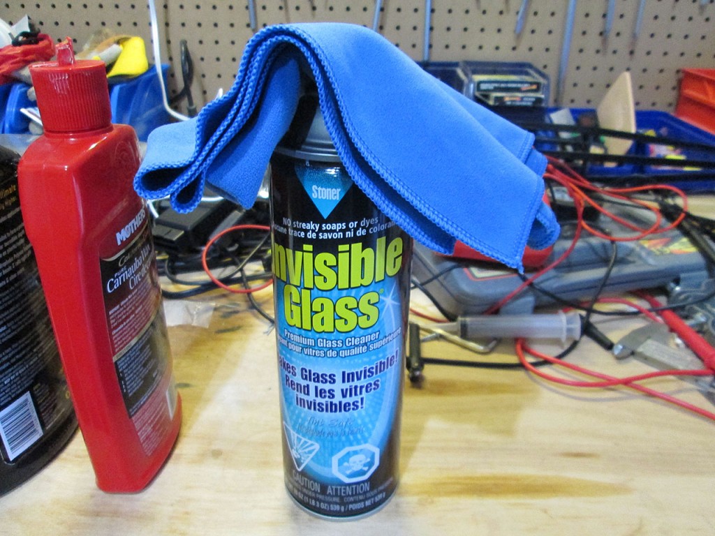
To clean the windshields and mirrors I use Stoner Invisible Glass and a very short fiber cloth. This combination leaves no streaks and is a quick 10 minute job to do all surfaces.
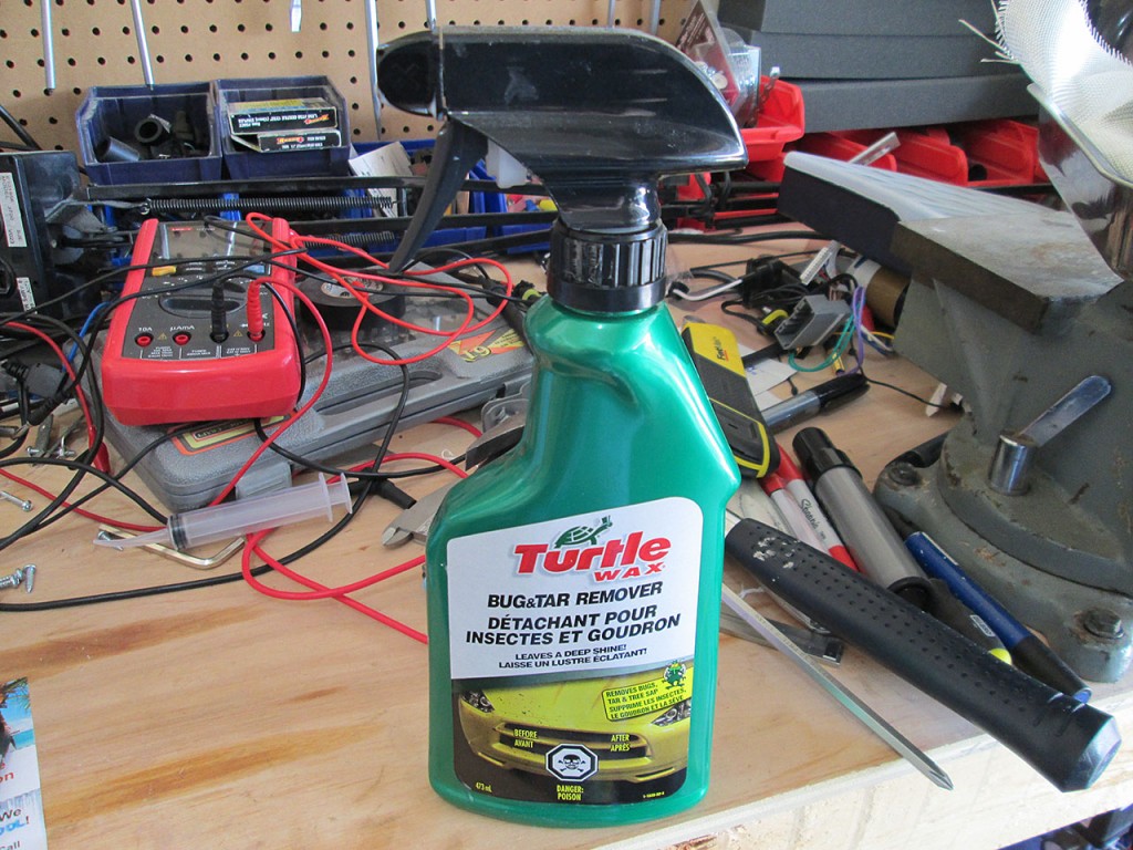
If the car hasn’t been detailed in a while it’s time to clean the tire wells. To remove any tire rubber or any residue I use Turtle Wax Bug & Tar Remover.
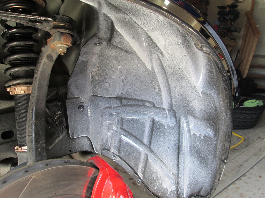
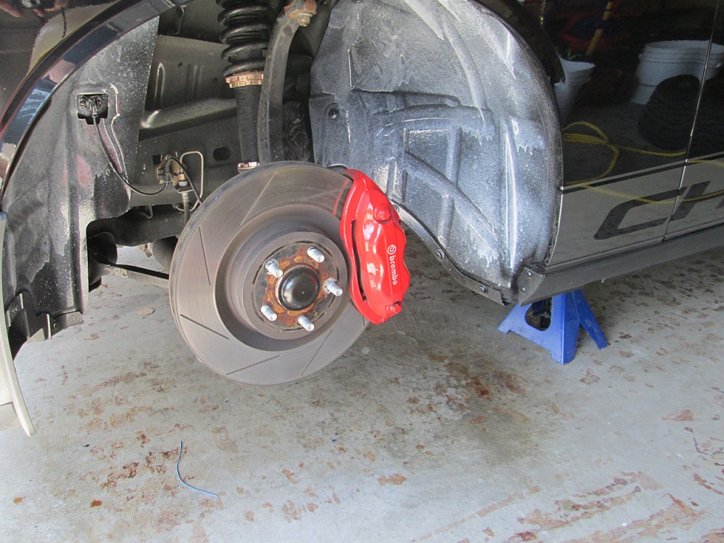
Simply spray a good amount on the surface to be cleaned and wait a few minutes for the remover to do its work.
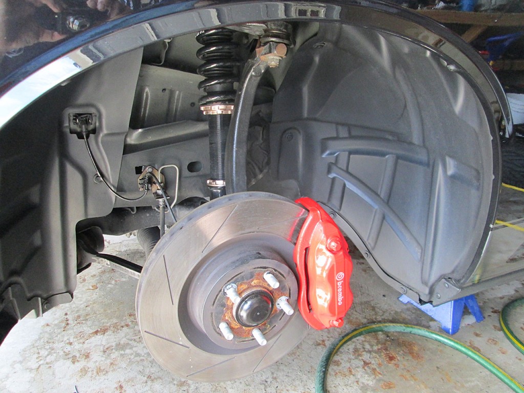
After few minutes simply use a cotton towel to wipe off the remover. I sometimes follow this process with a quick spray of Stoner Trim Shine to give the surface a bit darker, shinier look.
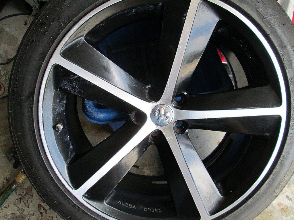
While waiting for the tar remover to do its job I clean the rims. If the rims are really dirty I’d use a spray on rim cleaner to remove the excess brake dust but typically just spray with water and wipe with microfiber cloths. I use a separate batch of cloths for wheels as the brake dust will scratch paint and it’s not a good idea to reuse them for working on the body. Once the rim is dry, I use synthetic wax on the rims. It helps to keep the brake dust from sticking to the rim.
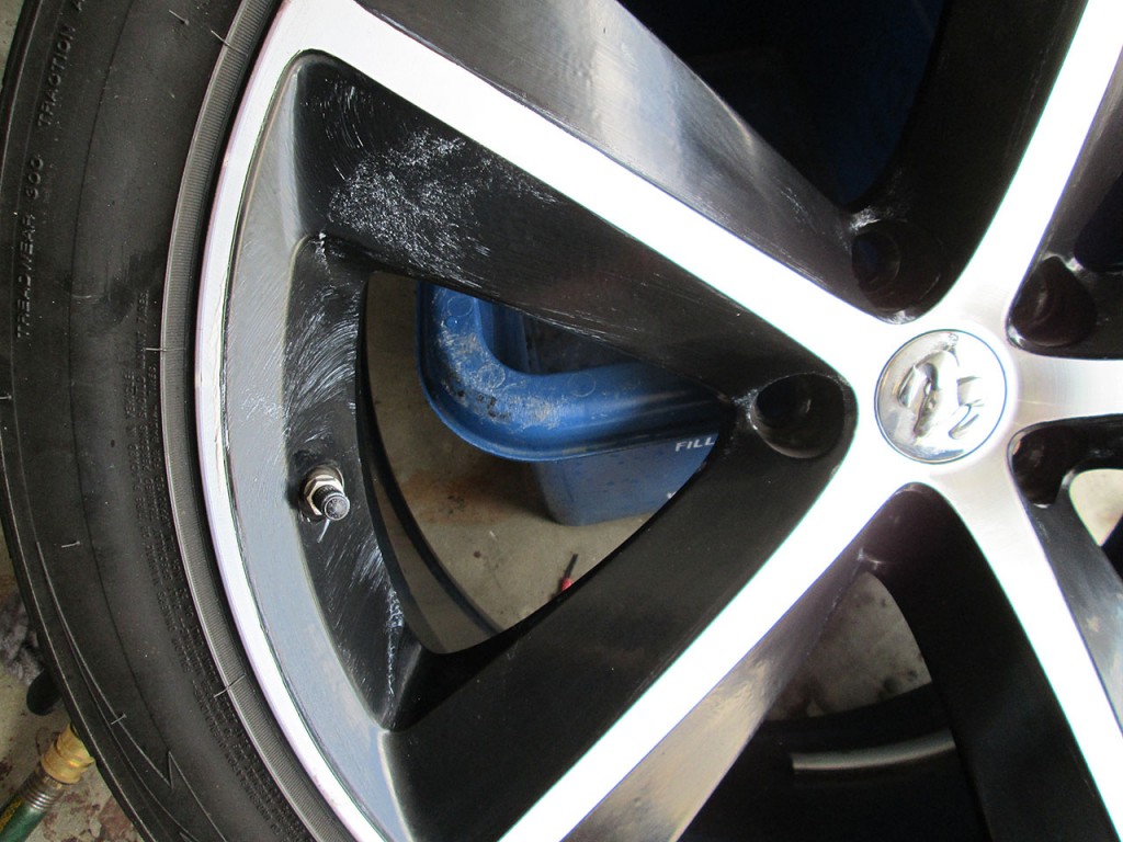
For the wheels I do not use Glaze. Just the synthetic wax. The process is the same as the body of the car. Apply the wax, wait for it to dry and then simply wipe clean.
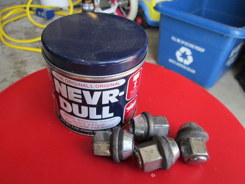
For lug nuts I use Nevr-Dull chrome polish. It’s perfect product for cleaning chrome surfaces and it’s very good at removing oxidation and any residue. For tires I use Black Magic tire wet. It doesn’t leave any residue on the tire when it dries and doesn’t cause the tires to crack like some silicone based tire sprays.
And exterior of the car is done. This process took about 20 hours total over the course of 4 days. The wax should last easily till fall depending on how much time it spends outdoors. The wax keeps the car cleaner, longer and car washes become very quick as the water and dirt easily roll off the paint.
Now for the interior of the car…..
Teensy + USB Raw HID + C# = Eureka!
I’ve spent at least 3 days converting my Amp Delay Service from Serial communication to Raw HID communication protocol. My CarPC was using at one point 5 COM ports for the various devices connected to it. Iw was becoming a real pain keeping track of each COM port and the actual device that it represents. So I decided to convert my devices to plain USB devices rather than Serial.
Everything was going great until I tried sending data to Teensy while converting the Amp Delay box. The Amp Delay service needs to ping the Teensy device but for some reason (which is still unknown to me) sending data to the Emulated Serial device doesn’t work.
I’ve tried a handful of 3rd party USB libraries, tried rolling my own, tried synchronous vs overlapped IO. Nothing worked. I just could not send data to the device.
After hours of Googling, I finally stumbled on a solution. Turns out that when Teensy operates in Raw HID mode it presents itself to the PC as two devices:
VID_16C0&PID_0486&MI_00 – Raw HID Device
VID_16C0&PID_0486&MI_01 – Emulated Serial device
The “Serial” object in Arduino can send data to the Emulated Serial device which is the method I used to send the Gauge Pod Sender data to the PC. There seems to be a problem however sending data from the host to the device over this protocol.
The correct solution was:
1. Connect to the RAW HID Device instead.
2. Use RawHID.send and RawHID.read in Arduino code to communicate with the host.
I completely accidentally stumbled upon the RawHID object. It is not documented ANYWHERE. The difference is that Serial.print sends data to the Emulated Serial device and RawHID.send sends it to the RAW HID device.
void SendHID(String text)
{

  uint8_t sendMessage[64]; //buffer
  text.getBytes(sendMessage, text.length()+1); //convert text to bytes

  //fill rest of buffer with zero
  for (int idx = text.length(); idx < 64; idx++)
    sendMessage[idx] = 0;

//send to PC, allow 100ms for sending the frame
  int sent = RawHID.send(sendMessage, 100);

}
Another interesting tidbit.
arduino-1.0.3\hardware\teensy\cores\usb_rawhid\usb_private.h
holds the VendorID and ProductID that can be changed. When the sketch is uploaded to the device the values are changed on it. This makes it easy to distinguish multiple Teensy devices on the same PC. By changing the Product ID I can have the Amp Delay box and the Gauge Pod sender uniquely identified and don't have to worry about the program connecting to the wrong box.
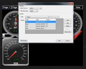
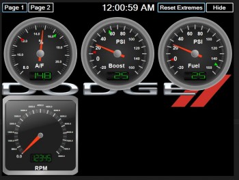
Gauge Pod 2.0 Development
Been busy coding away on the Gauge Pod software. It’s coming along nicely. I’ve taken a slightly different approach from the first version and the code is turning out to be a lot simpler. Still using layered architecture to separate Sensors, Gauges, Communication and UI but I changed how the layers interact with each other. The update performance has gone up dramatically. Using the Gauge Pod Sender in USB mode has also greatly reduced overhead and feeds data incredibly fast.
I’m currently in the testing phase of the software but looking good so far. The gauges are VERY stable compared to the last version. Will start testing the software on the car in the next few weeks as time permits. Can’t wait to try this in the car.
Gauge Pod 2.0 – Sender (pt 2)
I’ve spent about 2 days on dealing with the ADC (Analog to Digital Converter) of the Arduino platform. Turns out there’s more problems to overcome when dealing with taking analog signal from a sensor and converting it to meaningful digital reading.
The issue is that even with a constant input voltage the ADC reading sampling error rate is larger than I’d like (~1.2%) with some random spikes in excess of 3%.
I built a test rig to troubleshoot the issue. Using constant input voltage and a potentiometer to simulate the analog input from a sensor.
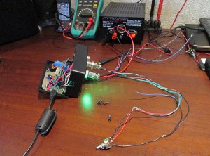
Goal:
– At least 4 sample updates per second. (Smooth gauge updates)
– Stable voltage regardless of outside interference.
Things I found:
– Arduino Atmel chip uses a single ADC and multiplexes the input pins.
– Switching read pin on the ADC causes noise in the system. Solution to read the first value and totally discard it. Then wait at least 10ms before sampling actual data.
– Sample accuracy is inversely proportional to the delay between samples. Shorter delay between reads, less drift. But over a static period of time, the error rate is the same.
– ADC is quite sensitive to electronic noise. Adjacent pins seem to affect reading.
Things I tried:
– Average voltage over multiple samples (currently 11 samples per read)
– Add delay between readings (1 to 12 ms) (currently 2ms)
– Discard top and bottom values and average the rest (currently discard 25%)
– Add a delta value, discard new value if difference is less than delta (currently 0.011V)
– vary delay on multiplex debounce (currently 10ms)
Current sampling rate: 3.7 samples / second.
Final Arduino Code:
const int LED_RED = 9;
const int LED_GREEN = 8;
const int LED_BLUE = 7;
const int LED_ACT = 11;
const int INPUT_REF = 22;
const int INPUT_RATE = 20;

int refPins[4] = {19, 17, 18, 16};
int sensePins[4] = {15, 13, 14, 12};
double lastRefVolts[4] = { 0, 0, 0, 0 };
double lastSenseVolts[4] = { 0, 0, 0, 0 };

const float LOW_VOLTAGE = 4.5; //alert voltage for 5V bus

const int MAX_SAMPLES = 50; //max sample on trim pot
const float DISCARD_PCT = 0.25; //percent of samples to discard (top and bottom)
const float MAX_DELTA = 0.011; //ignore changes less than this
const int SAMPLE_DELAY = 2; //delay MS between sample reads
const int INITIAL_DELAY = 10; //delay MS on pin change


void setup()
{

  //set pin IO modes
  pinMode(LED_RED, OUTPUT);
  pinMode(LED_GREEN, OUTPUT);
  pinMode(LED_BLUE, OUTPUT);
  pinMode(LED_ACT, OUTPUT);

  for (int pin = 0; pin < 4; pin++)
  {
    pinMode(refPins[pin], INPUT);
    pinMode(sensePins[pin], INPUT);
  }

  pinMode(INPUT_REF, INPUT);
  pinMode(INPUT_RATE, INPUT);

  //cycle leds
  digitalWrite(LED_RED, HIGH);
  digitalWrite(LED_BLUE, HIGH);
  digitalWrite(LED_GREEN, HIGH);

  setLED(LOW, HIGH, HIGH);
  delay(200);
  setLED(HIGH, LOW, HIGH);
  delay(200);
  setLED(HIGH, HIGH, LOW);
  delay(200);
  setLED(LOW, LOW, LOW);
  delay(200);
  setLED(HIGH, HIGH, HIGH);

  //emulated serial, speed ignored
  Serial.begin(38400);

}

void loop()
{

   //read serial to clear buffer
  if (Serial.available() > 0)
  {
    Serial.flush();
  }

  //get number of samples to read
  int readCount = getReadCount();

  //write +5V bus voltage
  writeRefVoltage(readCount);

  //write all input sensors
  for (int pin = 0; pin < 4; pin++) {
    writeSerialVoltage(pin, readCount);
  }

}

void writeSerialVoltage(int pin, int readCount)
{

  digitalWrite(LED_BLUE, HIGH); //blue off - start sending
  digitalWrite(LED_ACT, LOW); //internal off

  //ref volt, seems more volatile
  float refVolt = getVoltage(refPins[pin], readCount);
  float newRefVolt = processRefVoltage(pin, refVolt);

  //get sensor voltage
  float senseVolt = getVoltage(sensePins[pin], readCount);
  float newSenseVolt = processSenseVoltage(pin, senseVolt);


  Serial.print("IN");  //write identifier
  Serial.print(pin);
  Serial.print("\t");
  Serial.print(newRefVolt, 4);
  Serial.print("\t");
  Serial.print(newSenseVolt, 4);
  Serial.print("\r");
  Serial.println("");

  digitalWrite(LED_ACT, HIGH); //internal on
  digitalWrite(LED_BLUE, LOW); //blue on - sending done

}

//do a delta comparison on Ref voltage
float processRefVoltage(int Pin, float refVolt)
{

  float lastRefVolt = lastRefVolts[Pin];

   if (abs(refVolt - lastRefVolt) < MAX_DELTA)
     refVolt = lastRefVolts[Pin];
   else
     lastRefVolts[Pin] = refVolt;

    return refVolt;

}

//do delta comparison on sensor voltage
float processSenseVoltage(int Pin, float senseVolt)
{

  float lastSenseVolt = lastSenseVolts[Pin];

   if (abs(senseVolt - lastSenseVolt) < MAX_DELTA)
      senseVolt = lastSenseVolts[Pin];
  else
     lastSenseVolts[Pin] = senseVolt;

    return senseVolt;
}


//send bus voltage to host
void writeRefVoltage(int readCount) {

  float refVoltage = getVoltage(INPUT_REF, readCount);

  if (refVoltage < LOW_VOLTAGE)
  {
    digitalWrite(LED_RED, LOW);
    digitalWrite(LED_GREEN, HIGH);
  }
  else
  {
    digitalWrite(LED_RED, HIGH);
    digitalWrite(LED_GREEN, LOW);
  }

  Serial.print("REF\t");
  Serial.print(refVoltage, 4);
  Serial.println("");
}

//read value from ADC (0-1023) and convert to voltage (0-5)
float getVoltage(int PIN, int samples) {

  //allow ADC to stablize
  analogRead(PIN); //ignore value
  delay(INITIAL_DELAY); //wait for debounce

  float sampleList[samples];

  //read samples
  for (int i = 0; i < samples; i++)
  {
    float voltage = (float)analogRead(PIN) * (5.0 / 1024.0);
    //round to 2 decimals
    sampleList[i] = (ceil(voltage * 100.0)) / 100.0;
    delay(SAMPLE_DELAY);
  }

   //sort array (shitty bubble sort, cause i'm lazy)
    float swapper;
    for (int o = samples-1; o > 0; o--) {
        for (int i = 1; i <= o; i++) {
          if (sampleList[i-1] > sampleList[i]) {
          swapper = sampleList[i-1];
          sampleList [i-1] = sampleList[i];
          sampleList[i] = swapper;
        }
      }
    }

      //discard % of top and bottom values, average the rest
      int avgStart = max(samples * DISCARD_PCT, 1); //array start
      int avgEnd = min(samples * (1.0 - DISCARD_PCT), samples); //array end

      int avgSamples = 0;
      float ret = 0;

      //average out the values
      for (int cntr = avgStart; cntr < avgEnd; cntr++)
      {
        avgSamples++;
        ret += sampleList[cntr];
      }

      return ret / (float)avgSamples;
}

//read trim pot, get average samples
int getReadCount() {

  analogRead(INPUT_RATE);
  int readCount = analogRead(INPUT_RATE);
  return map(readCount, 0, 1023, 4, MAX_SAMPLES);

}


//set RGB led values
void setLED(int RED, int GREEN, int BLUE) {
digitalWrite(LED_RED, RED);
digitalWrite(LED_GREEN, GREEN);
digitalWrite(LED_BLUE, BLUE);
}
Binary sketch size: 7,196 bytes (of a 32,256 byte maximum)
Estimated memory use: 103 bytes (of a 2,560 byte maximum)
This is probably as close as I can get to get an accurate reading that doesn't jump around too much. Filters most noise while giving a decent sample rate. Currently reading all 4 inputs. Technically could reduce to 3 inputs since 4th won't be used for a while. Will see how well Gauge Pod software deals with current feed rate.
Gauge Pod 2.0 – Sender
I’ve started working on Gauge Pod 2.0 for the Challenger. The original version had some issues as described here.
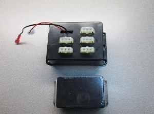
The original sender was located under the dash. Currently utilizes three sensors (AFR, Boost and Fuel Pressure). The box was built to support more sensors but in the end I ended up using only those three. I used 3 pin molex connectors which turned out to the a bad idea as the connections weren’t very secure. Additionally I had to make some last minute modifications to feed a 5V signal to the sensors. In the end the box was way too bulky and not terribly efficient.
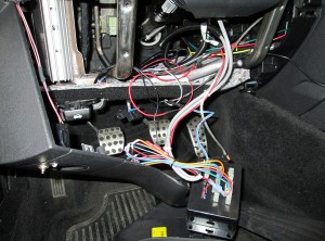
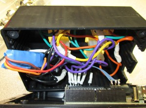
Due to the fact that the Arduino Diecimila uses pin connections (as it’s more for prototyping), the connections weren’t very good. While I had no problem with the connections themselves, I didn’t feel that this was sufficient for long term use. The next sender will have everything properly soldered.
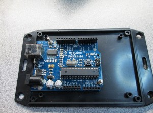
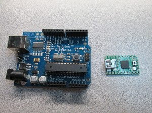
The enclosure I used was also too large even for the size of the board. The new Arduino board (Teensy) is tiny compared to the original board. Teensy is actually more powerful than the Diecimila board, as it offers double the RAM (whooping 2K), double the Flash (32K) and a lot of PWM outputs and Analog inputs. Additionally, the Teensy board can act as native USB device, no need for serial port emulation. It’s also quite cheaper than the official Arduino.
Sensor voltage is supplied via an RC BEC board from Castle Creations. The BEC can be programmed for any output voltage. Originally the board was programmed for 5.1V from factory. The BEC is most likely type of MOSFET voltage regulator instead of the more traditional linear regulator. This does introduce a bit of noise into the system as the PWM system typically operates in the Khz range. Though, with bench testing I didn’t see any significant problems with this.
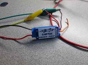
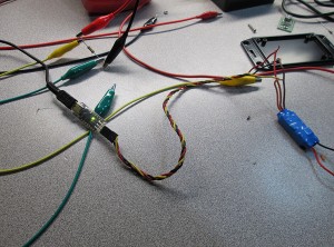
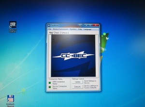
I didn’t actually realize right away that I had a programmer for the BEC. I picked one up last year for my Mamba Pro ESC. With just a few clicks of a button I was able to program it for 5V.
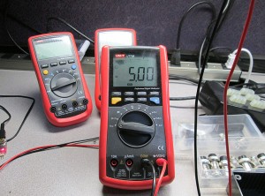
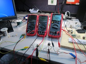
One of my theories for the flactuating voltage is that one or more sensors was putting too much load on the BEC. During testing I noticed that with higher amperages the BEC supplied voltage would drop. At 0.7A the voltage dropped to almost 4V. This was quite unusual since the BEC is rated at 10A. To mitigate this problem I’m using some inline, low ohm resistors to current limit the supply. This should prevent excessive load on the BEC.
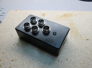
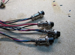
For the input voltage and sensors I’m using 2 and 4 pin barrel connectors.
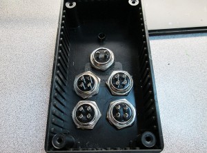
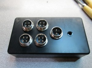
Connector Pinouts:
Sensor Input Barrel Connector:
1 – Black – Ground
2 – Red – +5V
3 – Blue – +5V (Current Limited)
4 – Green – Sense In
Power In Barrel Connector
1 – Black – Ground
2 – Red – +12V (ACC)
Teensy Sensor Pins:
| Input | Sense Pin | Ref Pin |
| Input 1 | 15 | 19 |
| Input 2 | 13 | 17 |
| Input 3 | 14 | 18 |
| Input 4 | 12 | 16 |
I’m also using an RGB LED for status indicator. The LED uses a common anode, so the LED turns on when driving Teensy pin LOW.
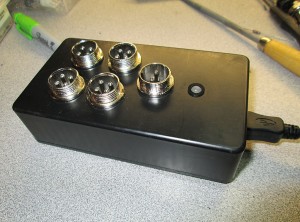
LED Pins on Teensy:
Common Anode: 5V
Red: 9
Green: 8
Blue: 7
Internal: 11
The Blue indicator blinks when new voltage data is sent. The Green indicator is on when the sensor supply voltage is above 4.5V. The Green indicator changes to Red if the voltage drops below 4.5V
I’m using a small perf board to solder all the components on. There’s not much to it. A few 1/4W resisitors for current limiting sensors, few resistors for the RGB LED and a trim pot for adjusting data rate.
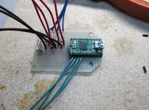
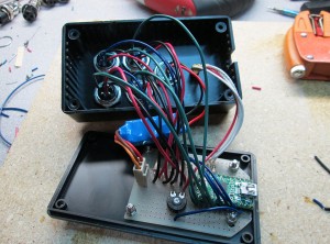
The box all done. There’s a small hole on the side for the mini-USB connector that will connect via USB cable to the carputer. This will in turn be read by the Gauge Pod software, parsed and displayed as an analog gauge on the screen.
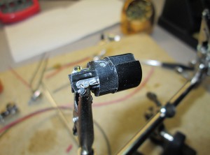
Last step was to solder up some of the female connectors that will be spliced into the Challenger itself. Just three sensor connections for now. I might add oil pressure sensor later down the line.
Thanks to the use of the reference voltage on each input any fluctuations of supply voltage and ADC error will be smoothed out. The Arduino sketch is very simple. The sender simply sends tab delimited data to the USB device in the format:
{INPUT}\t{REF_VOLT}\t{SENSE_VOLT}\r\n
e.g. IN1\t5.00\t2.00\r\n
This is repeated for each sensor input and finally sends the supply voltage: REF\t5.00\r\n
Final Features:
* USB HID Device. No more COM ports, no drivers needed.
* Reference Voltage on all inputs
* Reference supply voltage for each sensor
* Variable sending speed via trim pot
* Low Supply Voltage Indicator (less than 4.5V)
* Serial sending / Keep Alive Indicator
* Vibration proof screw-in type connectors
* Dual Current limited/non-limited sensor connectors
With the sender box complete, the next step is to re-write the Gauge Pod software to fix some of the issues and add some additional features.
Traxxas Slash + 1W LEDs
A while ago I was browsing parts in a local hobby store and I came across an RPM part for my Traxxas Slash. It’s an offroad light bar (RPM #80922). The product is meant to be used with typical 3mm LED’s, in fact, RPM sells an LED kit that fits the canisters. Looking at the LEDs I knew the LEDs were for show only as the LEDs included don’t do much for illumination, typical 3mm LEDs produce between 1500 and 3000 mcd of light intensity with a rather narrow beam of light. Looks pretty, but that’s about it.
As soon as I saw this I knew I could take it to the next level. As I always say, if something is worth doing, it’s worth overdoing. So as soon as I got home I went on eBay and picked up a set of these puppies.
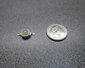
These are 1W Ultra Bright LEDs with built in heatsinks. These babies produce over 8000 mcd of light. Not only that, they have an extremely wide angle of view. These LEDs are blindingly bright, a perfect choice for some illumination for the truck.
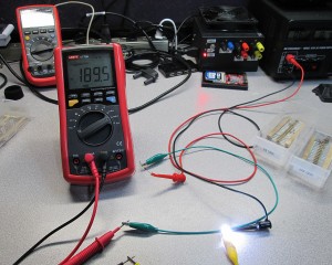
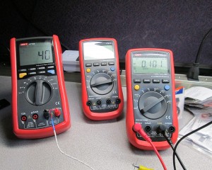
First step is to determine the best heat/brightness ratio. I did this by trying various values of resistors to get best brightness while maintaining heat at constant temperature. The LEDs in the canister will not be able to sink any heat. I used a thermal probe to get a reading on both the resistor and the LEDs heatsink. I ended up going with 22 ohm 1/4W resistors. After an hour under load the temperature was stable at 50C on the resistor and about 44C on the LED’s heatsink with ambient temperature of about 26C (toasty next to the servers).
I was having trouble finding some low gauge wire that I could use for the individual LEDs. The only thing I could find on spools was 24AWG which was still bit too thick for my liking. I stumbled across a roll of ribbon cable with what looked like 30AWG wire. It was perfect.
Soldering the LEDs was very quick and painless as the built in heatsink on the LED took care of protecting the LED from the heat from the soldering iron. The L#D canisters have a small hole in the back, the ribbon wire had no trouble passing through.
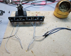
The next step is to solder the resistors inline. The best way I figured is to stagger the resistors so that when held together they don’t create a fat bundle.
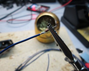
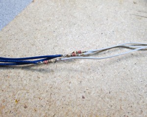
After that it’s just a matter of going to town with heatshrink to isolate all connections
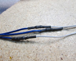
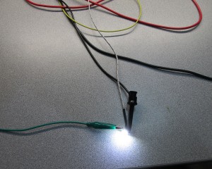
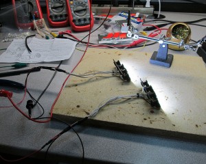
Before permanently affixing the LEDs in their respective canisters I needed to test the connections and make sure all LEDs light up.
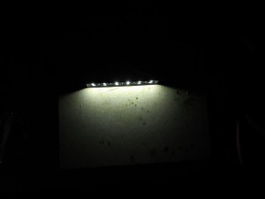
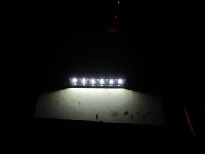
Once I confirmed that all LEDs are working properly, it was time to affix the LEDs to the canisters. I decided to use 30 minute Epoxy to give me plenty of time to align the LEDs properly.

What I missed though is that mixing a larger batch of epoxy causes a MUCH shorter curing time. In fact, the epoxy started to set just minutes after mixing the batch. I tried to work quickly applying the epoxy to each canister before the batch became unusable. The results were less than stellar. At least I still had time to align the LEDs but it was too late to try to remove some surplus.
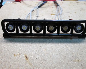
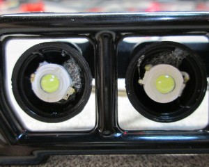
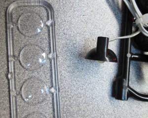
The RPM kits came with lenses that can be used with the LED canisters. Unfortunately due to the size of the 1W LED, the lens can not be used in this configuration. Which I don’t think it’s a big deal, I can see the cheap plastic lens getting scratched and becoming opaque in very little time.
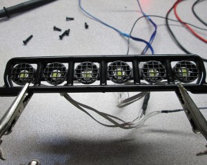
The grilles on for the canister fir perfectly though. Good thing too because it hides some of the ugly spillover epoxy inside the canisters. Mixed a much smaller batch this time so I had plenty of time to align the grilles.
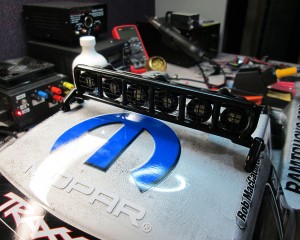
Once the epoxy has cured it was time to attach the bar to the body and do final testing. The light bar actually fits very nicely on the truck.
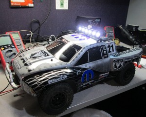
Shortly after I did this build I decided to take another step and add the bumper lights. Plus a friend asked me to do a set for him too. Back onto eBay to pick up RPM #80982 and few extra LEDs.
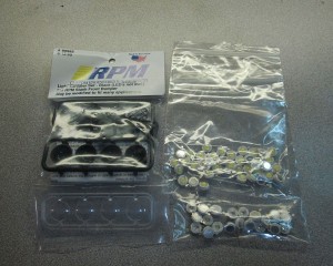
The process was pretty much the same as building the top light bar.
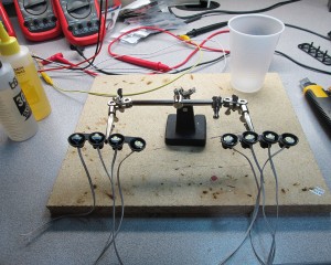
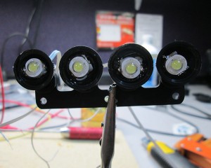
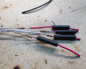
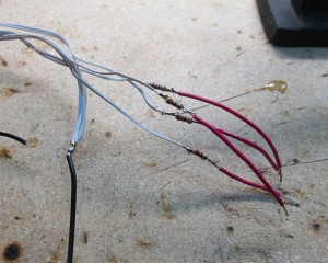
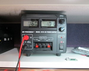
Once all wiring was done. It was time again to test the new LED arrays. Once again, zero problems with soldering these things. Just 8 LEDs in an array gobbled up a full 1 AMP of current. Having 10 LEDs on the truck will definitely put the receiver connection at a strain.
Just like the top bar, the lenses were skipped due to LED size, but the grilles went on without issues.
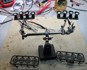
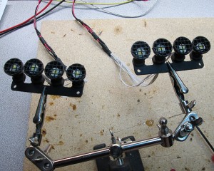
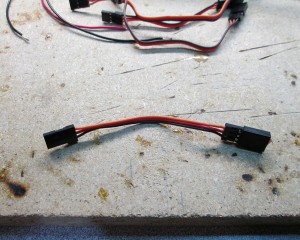
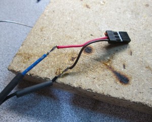
Last step was to solder up some Futaba/JR connectors to the LEDs for easy connections. I’ve used some servo extensions to do the job. Just cut off the male connector and solder the female to the LED leads.
Time to do final mounting to the truck. Routed the wiring through the H frame.
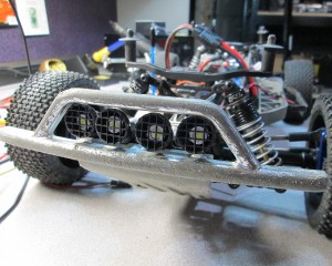
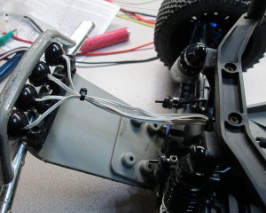
The RPM kit fits perfectly in the bumper using existing screw holes. The LEDs are definitely bright. It huts my eyes just looking at them.
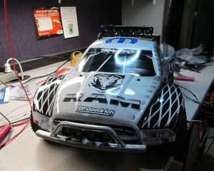
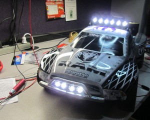
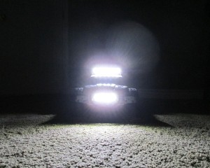
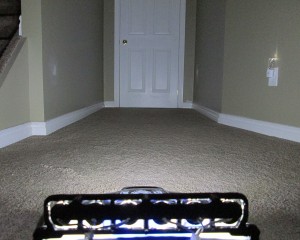
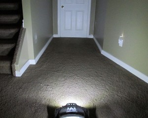
Some night shots. The camera really doesn’t do it justice. These LEDs are very, very bright.
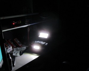
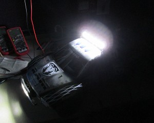
Some quick snaps showing just how much illumination these things provide. Other than the little night light these were taken in near perfect darkness.
pfSense on Watchguard Firebox x5000
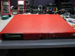
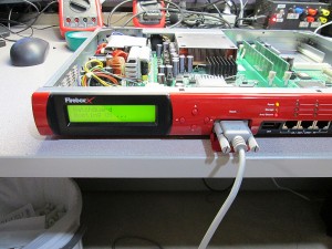
It’s been a while since I played around with firewalls. Picked up a really cheap Watchguard Firebox x5000 Peak on eBay. Could not resist taking the Peak platform for a spin with pfSense. I’ve heard good things about the power of the “Peak” platform. Even though the x5000 is older generation than the typical x550/x750s I’ve been playing with.
Unlike the x500 which comes with only 10/100 Realtek (problematic) interfaces. The x5000 is equipped with 3x 10/100/1000 nics and 8x 10/100 nics, all by Intel.
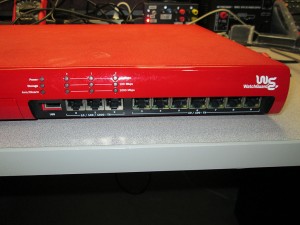
This box also comes with a second COM port at the rear of the unit. Though it serves no real purpose when running pfSense as all output is defaulted to COM1.
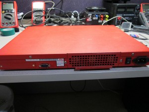
This firewall is actually just slightly shallower than the x750e series boxes. The x750 firewall is just a bit too deep for wall mount racks and required a right-angle power cable in order to fit. The x5000 is about an inch shorter.
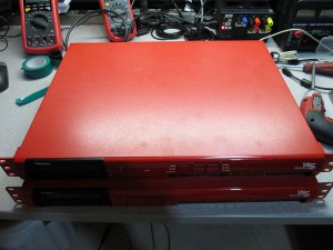
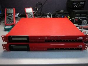
Taking the cover off exposes all the various components of this box. The Intel NIC chips can be clearly visible.
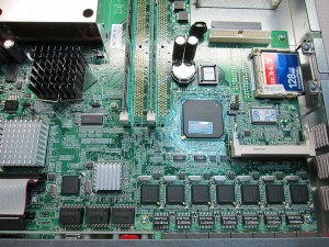
The “Peak” comes with 512MB of RAM standard. Unfortunately I could not locate any more DDR RAM to upgrade it, so for now will stick with the stock amount. I used to have tons of original DDR RAM modules, but got rid of them thinking I’m never gonna need them again.
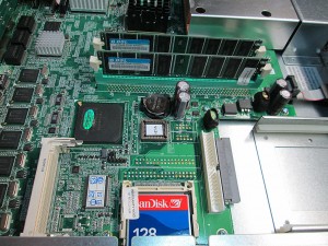
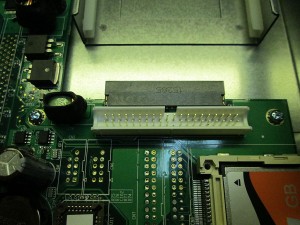
Just like most other boxes. This one comes with a 128MB Compact Flash card. And just like most of the other boxes, the IDE port is available for additional internal storage.
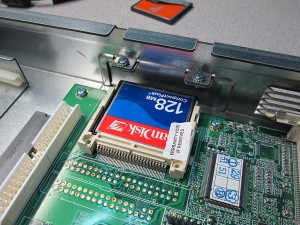
I wanted to take a quick peek at the CPU. Specifically to see what the stock CPU is. What I discovered was quite shocking. First of all, I had a problem getting the heatsink off from the CPU. Ended up tearing the heatsink and CPU directly from the ZIF socket. Closer examination revealed the cause of the problem. The amount of heat paste on this thing is insane. The gap between the heatsink and CPU was at least a couple of millimeters. It was everywhere. Someone really went to town on this sucker.
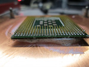
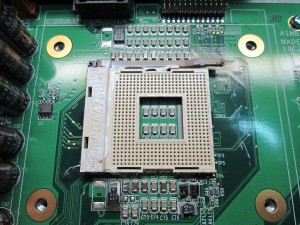
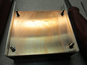
It took me almost 30 minutes to clean the CPU, heatsink and motherboard from all the thermal compound. I used plenty of rubbing alcohol and tons of cloths to get everything cleaned. Everything was completely covered with the goop.
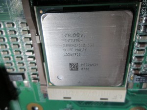
The CPU could finally be identified. Intel Pentium 4 2.8Ghz SL6PF. Not the most energy efficient CPU, quite the opposite. This firewall definitely sucks down a lot of juice. It’s actually a pretty fast CPU for the task. With firewalls raw speed matters most when dealing with latency. This one has plenty of speed.
Loading pfSense on this firewall is incredibly easy. There’s no BIOS flashing required. It boots pfSense from a 2GB CF card without any problems at all. Unlike the x500 firewall, which has Realtek NICs and randomly stops responding, the Intel NICs are bulletproof.
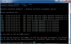
Once I got the firewall configured. It was time to do some throughput testing. I was expecting the speeds to be sub-par simply because both the 1000Mbit and 100Mbit interfaces are all on the PCI bus. PCIe did not exist in P4 era.
The interfaces on pfSense are identified as follows.
em0-em2 = 10/100/1000 NICs
fxp0-fxp6 = 10/100 NICs
Interestingly enough, the 8th 10/100 NIC does not appear in the list of devices. Not sure if this is due to pfSense limitation or a problem with the port itself.
On with the testing. The test was performed by copying a 8GB file between two machines. Both machines stored the file on an SSD to eliminate the disk as the bottleneck. The test was performed 3 times for each direction and values averaged over the test.
| Source Interface | Destination Interface | Transfer Speed | CPU Usage | |
| fxp0 | em0 | 10.3 MB/s | 20% | |
| em0 | fxp0 | 11.5 MB/s | 21% | |
| em0 | em1 | 42.8 MB/s | 41% | |
| em1 | em0 | 97.8 MB/s | 100% | * |
| fxp0 | fxp1 | 11.5 MB/s | 27% | |
| fxp1 | fxp0 | 11.5 MB/s | 27% |
* pfSense UI interface stopped responding during the transfer.
Once again it’s been shown that the bottleneck is the PCI interface. With maximum theoretical speed of 133 MB/s shared across the PCI bus, the firewall will never be able to attain faster combined throughput than roughly 100 MB/s. This is not terrible though for a small network as that kind of saturation is rather rare. What I can’t explain is why pfSense shows different max speeds depending on direction of data. This technically shouldn’t make a difference. I saw the same thing happen when benchmarking the x550e firewalls.
In the end, this is actually a pretty sweet box for what it costs nowadays. Even with “only” 512MB of RAM it’d be sufficient to run a small rack. However I do not recommend it for office use. The fans run 100% speed all the time and are fairly loud, haven’t found a way to throttle the fans other than replacing them with something quieter. The box, running pfSense draws about 52W at idle and almost 100W under load.
GaugePod – Rev 2
I’ve been spending a lot of time lately thinking about how to best redo my GaugePod program for my Carputer project.
Existing Problems (and potential solutions):
Program sometimes crashes on resume from hibernate.
Need to determine what causes this. This started when upgraded from Atom to I3 Motherboard/CPU. Perhaps Mobo not sending proper signal to Windows?
Current Arduino implementation isn’t very accurate.
This one is major. Had to fudge the voltage numbers to get semi-accurate reading. This needs a rewrite. Right now the Arduino box simply sends the raw value from the ADC (0 to 1023) as input into GaugePod. Perhaps a better solution would be to have the Arduino send the actual voltage. In fact, I could monitor the reference voltage to make sure it doesn’t drop below 5V. Arduino could detect any drop in reference voltage and adjust reading before sending to the Carputer. Could even add an LED to indicate a condition where reference voltage is not 5V, though it wouldn’t know if input voltage is >5V. Though that is highly unlikely as the reference voltage is coming from a 5V voltage regulator.
Change how GaugePod stores settings locally.
Right now the settings are stored in a DataSet that’s stored in the user profile. Can’t migrate settings or even hand edit. Need the ability to import/export settings. Switch to XML Format. Will have to write a custom library to deal with this. Won’t be difficult. Already did this kind of implementation in the UltraDMM project.
The Arduino box is too big and wiring too complex.
Need to simplify wiring, switch to Teensy for smaller footprint. Perhaps add chokes to eliminate electronics noise. Rev 2.0 of the Arduino box uses Molex connectors for the sensors.
Better to use barrel connectors. Need 3 Pins.
1 – 5V Input
2 – Ground
3 – Sensor Return
Something like this would work:
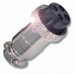
Additional advantage of using round connectors. Easy enough to drill holes for them rather then cut square holes for the Molex connectors. The enclosure would be nicer looking. The screw-in connectors would deal better with vibration in the car.
Program runs in foreground, blocks access to Centrifuse
Possible solution to implement as plugin for Centrifuse. Though it might be possible to simply run the program inside a Centrafuse window. I vaguely remember reading that this can be done. Drawback of this approach is reduced screen real-estate.
To Be Continued…..


