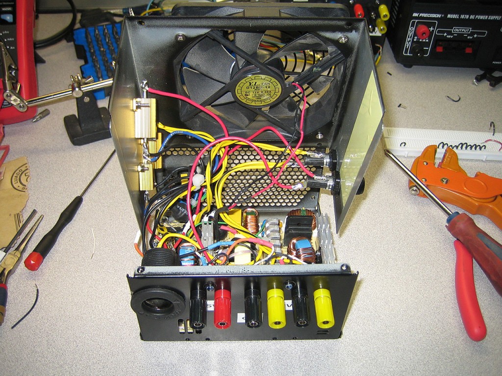
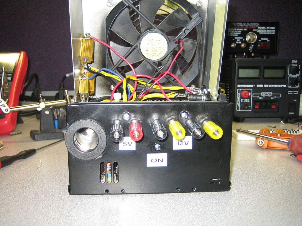
Wiring
This is where it gets interesting. Switching power supplies always must have a load on the rails. This is typically not a problem when they’re connected to the computer as they always have a load but because we’re fooling the supply into thinking it’s still connected, we must provide a dummy load in case the supply is turned on with nothing connected to the binding posts. These power resistors have been selected to always provide a 1A load on each rail (3.3, 5V and 12V). This equates to about 12W at 12V so these do get HOT when there’s no load on the binding posts. Fortunately, the power supply enclosure will provide as a heatsink for these.
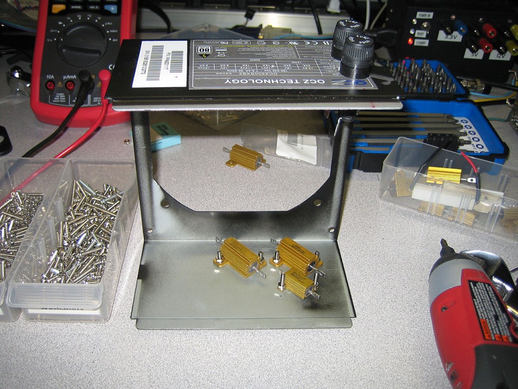
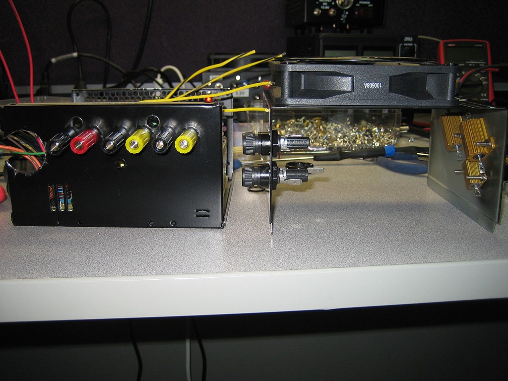
Also added additional protection to the 5V and 12V rails. A pair of 25A fuses will protect each rail. The 3.3V rail will not require a fuse as it will not be utilized.
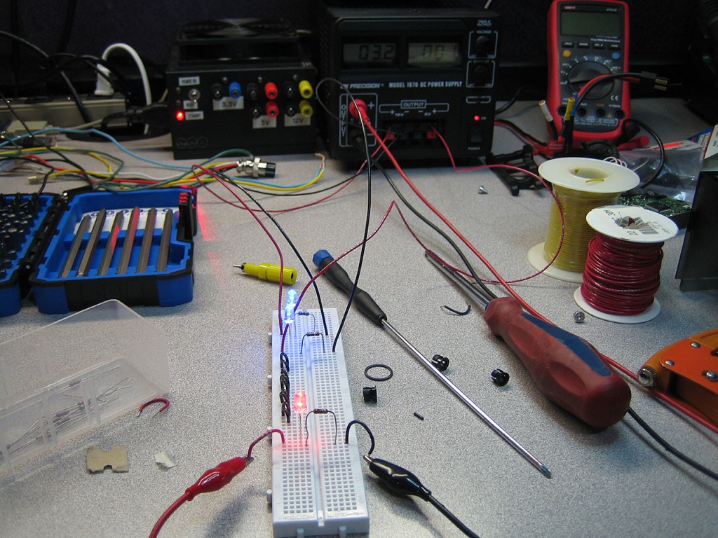
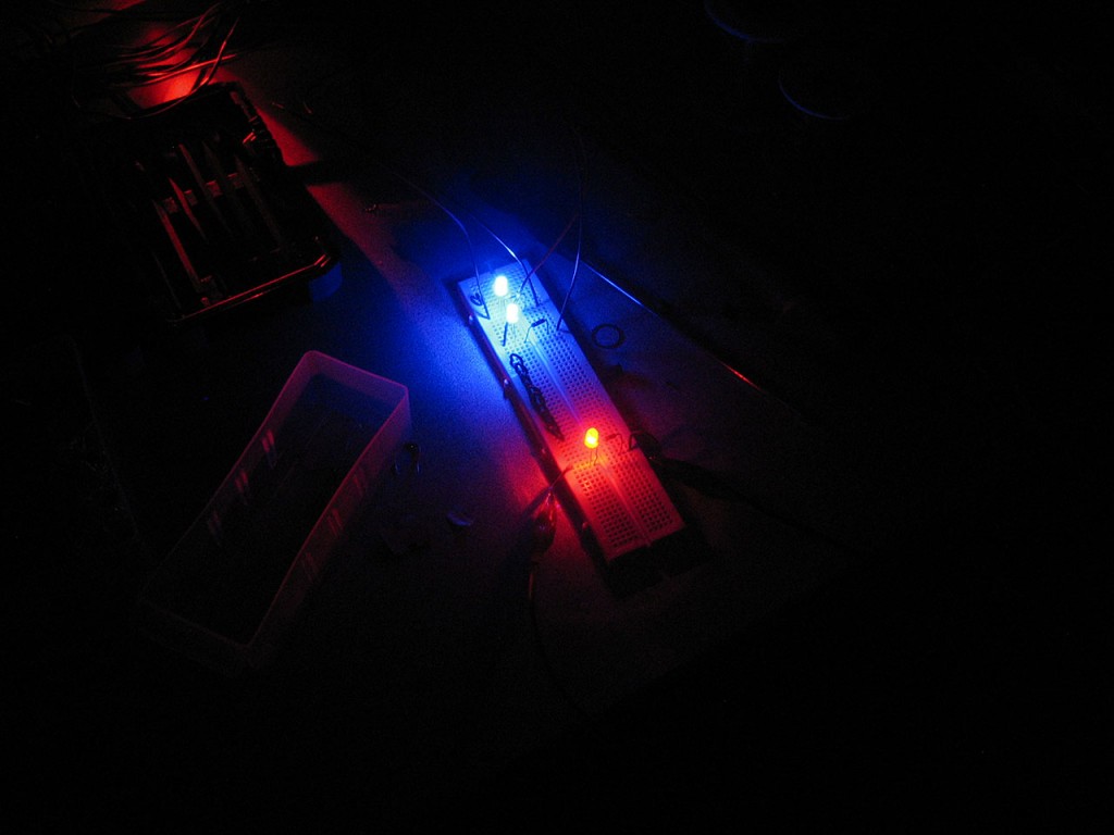
Because the LED indicators will be used on both the 5V and 12V rails, I needed to size the resistors for each LED so that the relative brightness of each is the same even though each LED will be receiving different input voltage. I built a quick jig to let me swap out different resistor values to get the brightness of each LED just right. The Blue LEDs might be overdone by now, but I still have quite a few of them left so I might as well use them up.
Started wiring everything. The wires from the supply to the load resistors are unfused since it’s important that the supply is always loaded. The fan has been mounted on the outside of the enclosure due to space constraints.
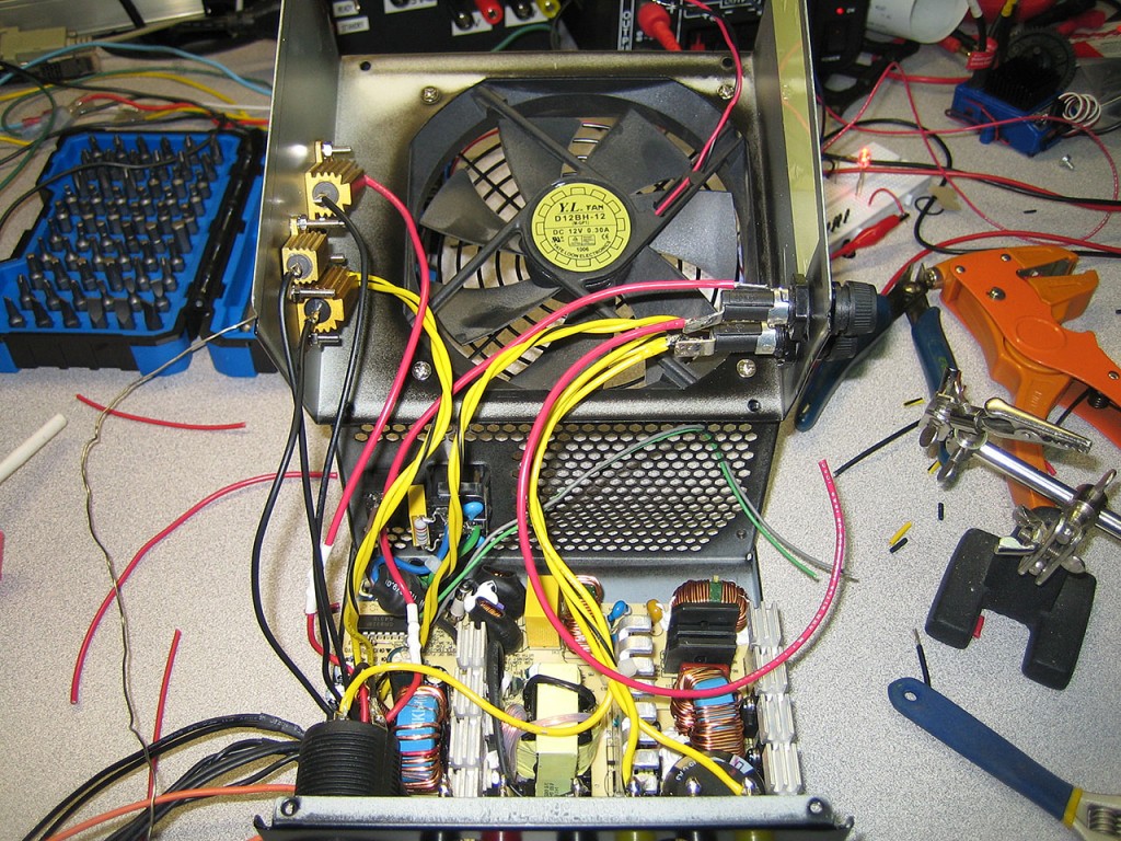
Wiring all done. Led’s installed and fan wire spliced back in. Tried keeping the wires as short as possible while still retaining the ability to open up and service the interior if necessary.
