A while ago when I first got into RC Cars I installed lights for one of my Traxxas Slash 4×4’s. The lights worked great and the look of the truck was a big hit at races and during bashing, but it wasn’t original. I wanted to do something a bit better, then totally over-do it.
I remember reading a while ago about Arduino’s ability to communicate with RC devices. Specifically it’s ability to read the receiver signal and also control Servos. With that in mind I started planning a control circuit to drive a lot of high power LEDs with the ability to control the lights remotely via the transmitter using the Teensy micro controller as the driver.
First problem was coming up with a way to drive the LEDs without frying the delicate Atmel processor. The easiest solution are of course MOSFETs. These babies can drive insanely high currents and best of all can be driven via an analog channel so the lights can be dimmed. This analog signal ability would allow for a plethora of light pulse combinations. They are very efficient and even a small TO-92 package can drive relatively high loads.
Second obstacle was to power the Arduino from an external source. The supply voltage was unknown and needed to be regulated. I wanted to make it as versatile as possible and have it powered either from the BEC or directly from the battery. The input voltage technically could be anywhere from 4.8V to 12V (Max 3 Cell Li-Po). First idea was to jam a linear voltage regulator like LM7085 into the mix. But that would require two additional caps and the TO-220 package is a bit big and I was trying to keep the size to a minimum and ideally was trying to fit everything in an Hammond Enclosure (1.97″x1.97″x.79″). The LM7805 is also a bit overkill to drive the Teensy since it barely draws 100mA. The solution was to use a simple Zener diode circuit to clamp the voltage to 5.1V.
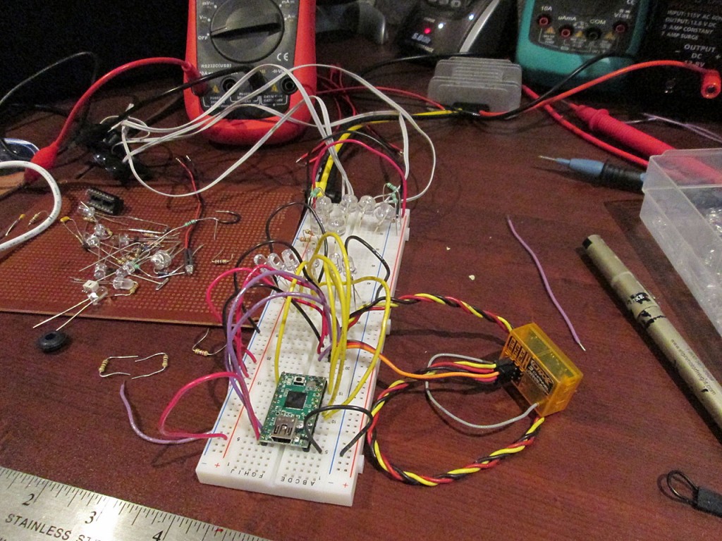
Once the circuit was designed, I built a prototype on a bread board and went on to write the Arduino Code required to control the channels via the RC Transmitter. One interesting thing I discovered during debugging is how many frames the receiver decodes that are invalid. When viewing the data stream from the receiver I saw a lot of blanks sent by the receiver to the servo channels. I didn’t think much of it at first but during prototype testing phase it showed up as LED glitching. At moments when the LEDs were supposed to be off they would randomly flash for a brief second. Tweaking the code to simply ignore blank frames quickly eliminated the glitching issue.
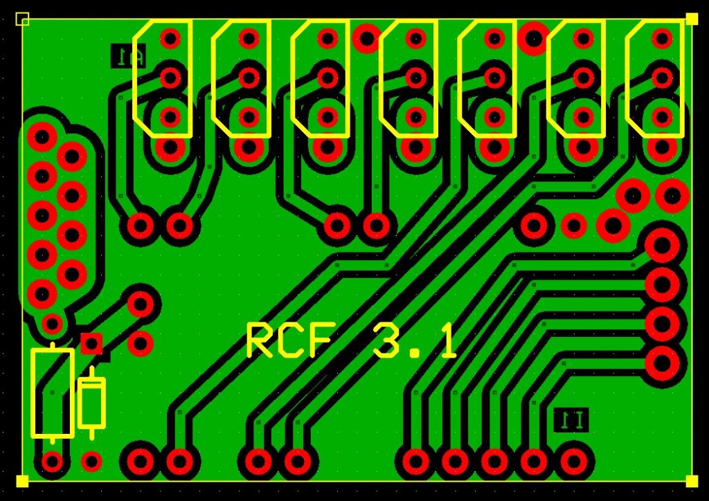
After few days of testing the design and tweaks to the Arduino code it was time to lay out a PCB board for manufacturing. I’ve gone through 12 revisions of the board using various MOSFET packages and varying the number of channels the box could read and number of channels the box would drive. In the end I settled on 4 input channels and 7 output channels (6 Analog, 1 Digital). After few days of mucking around, I finally came up with the final layout.
The manufacturing (etching) process is very simple. I used a similar technique used here. Instead of photo paper I switch to using magazine paper as apparently sometime in the near past most manufacturers started waterproof coating the photo paper making the transfer of toner to PCB very difficult.
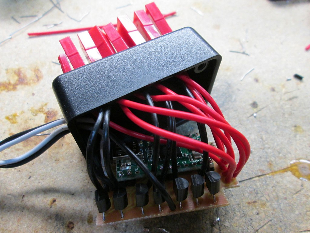
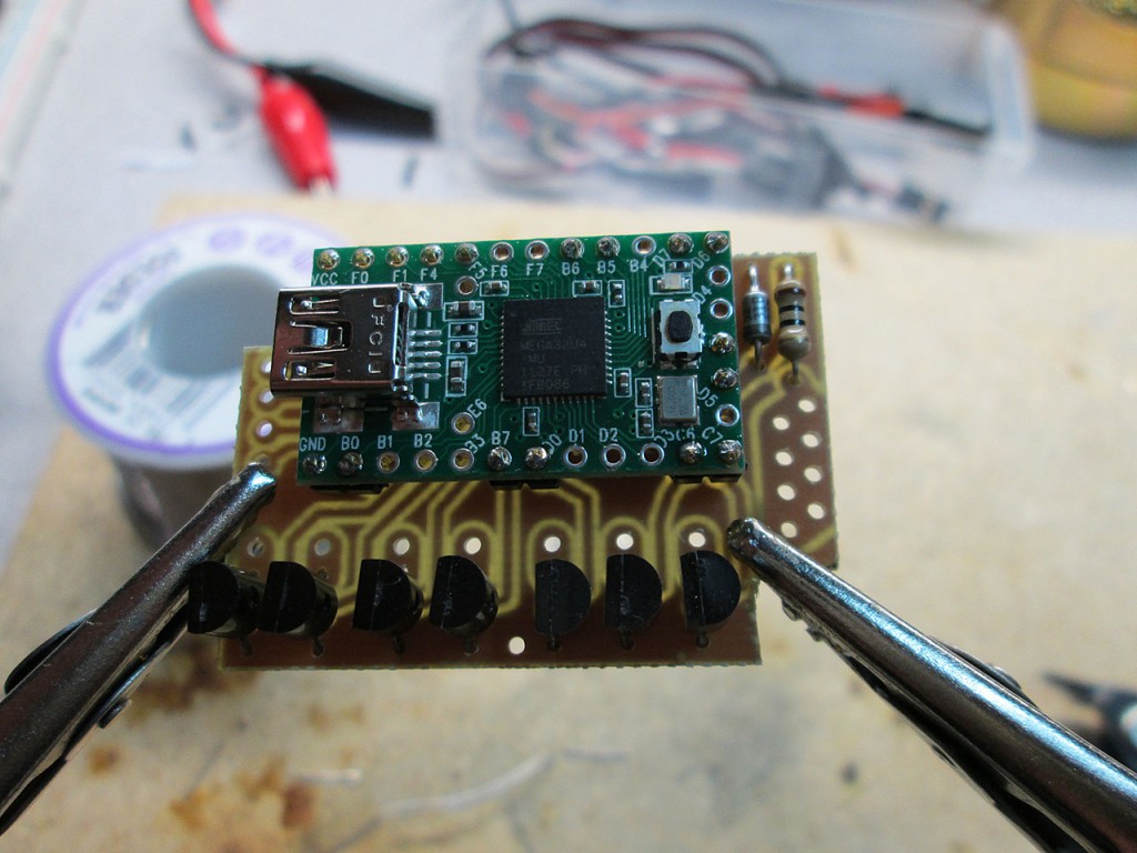
Once I had the PCB etched, tinned and the through holes drilled. I went on to solder the components in place. I ended up going with BS170 MOSFETs as they offered best power/cost ratio. At 500mA constant current per channel the system could effectively drive 3.5A. More than enough to drive LEDs and even small devices (more on that later).
For output connections I decided to use Micro JST plugs. They’re common in RC world, are small enough and incredibly resistant to vibration which is important in an RC Car. For the first prototype I used 2 input channels Throttle and Aux 1 to drive my LEDs.
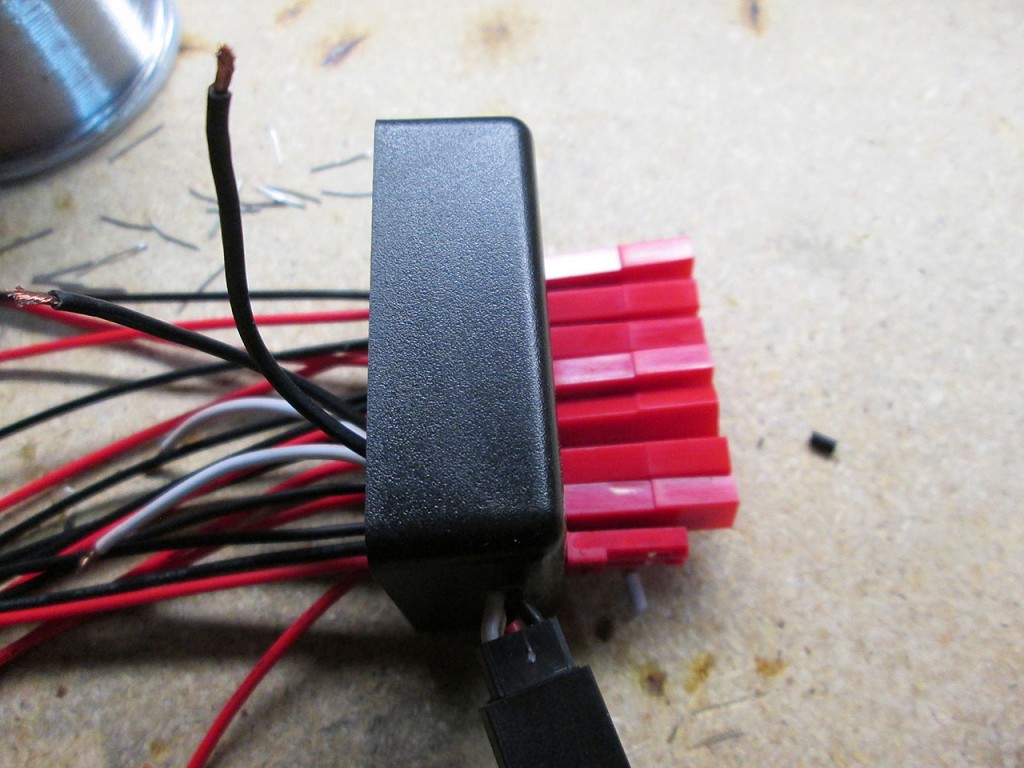
It’s a pretty tight fit but everything fits into the small enclosure as planned.
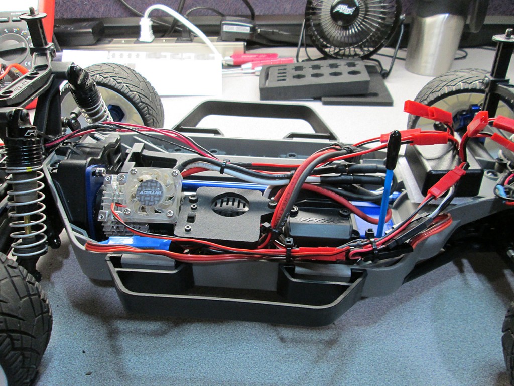
Once the assembly was completed it was time to mount the box into the RC Car. In my case this is a Traxxas Slash 4×4. This car is the LCG version of the Slash and as it turns out the LCG version does not have a lot real estate available for external electronics. I built a small tray in front of the chassis and used hook and loop material to secure the Flasher box. I used Castle BEC to drive the circuit and the LEDs. I programmed the Castle to 6V to drive more current per watt.
The car uses 4x 1W White LEDs on the bumper of the car. These LEDs are split into two groups that take up two channels on the box.
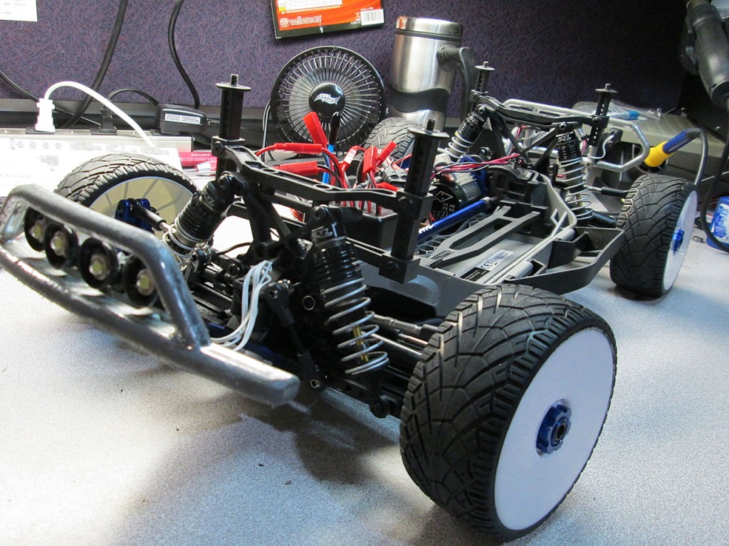
The rear lights are also 1W Red LEDs. These individually take up 1 channel each.
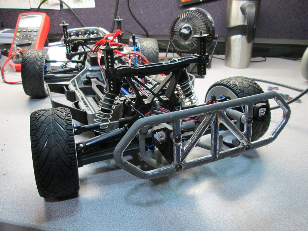
Two more channels are taken up by LEDs mounted on the prototype body of the car. The LEDs on the car are 1/2W Blue and Red LEDs.
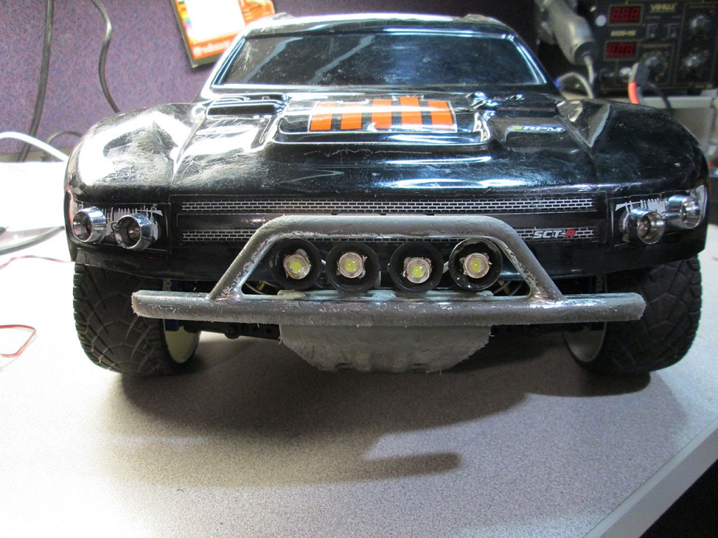
All this combined gives me the following features.
1. Working brake lights. The rear lights will come on with sufficient reverse throttle
2. (Mode 1) Head lights / rear lights. With functional brake lights
3. (Mode 2) Cop Mode. The lights will flash just like a police car.
4. Battery Reminder. The BEC is connected directly to the battery connector without a switch. When the truck is off, The brake lights will fade in/out as a reminder to disconnect the battery.
Here’s a short video of the RC Flasher in action.

Pingback: RC Flasher Project | Altered Realms
Pingback: BThunderW's Hardware Stuff - Page 3
Pingback: New RC Car – Vaterra Kemora | Copy Error (aka Altered Realms)