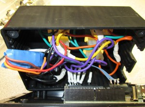
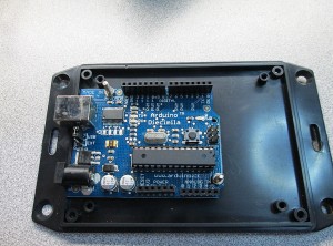
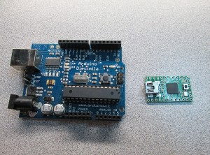
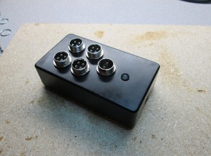
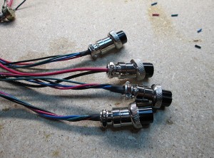
I’ve spent about 2 days on dealing with the ADC (Analog to Digital Converter) of the Arduino platform. Turns out there’s more problems to overcome when dealing with taking analog signal from a sensor and converting it to meaningful digital reading.
The issue is that even with a constant input voltage the ADC reading sampling error rate is larger than I’d like (~1.2%) with some random spikes in excess of 3%.
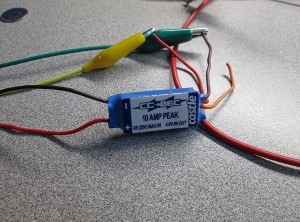
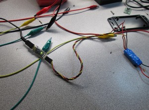
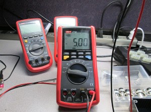
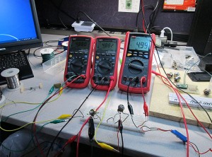
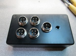
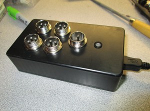
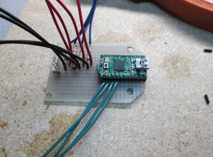
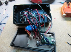
I built a test rig to troubleshoot the issue. Using constant input voltage and a potentiometer to simulate the analog input from a sensor.
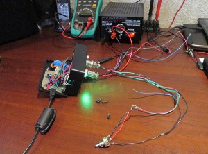
Goal:
– At least 4 sample updates per second. (Smooth gauge updates)
– Stable voltage regardless of outside interference.
Things I found:
– Arduino Atmel chip uses a single ADC and multiplexes the input pins.
– Switching read pin on the ADC causes noise in the system. Solution to read the first value and totally discard it. Then wait at least 10ms before sampling actual data.
– Sample accuracy is inversely proportional to the delay between samples. Shorter delay between reads, less drift. But over a static period of time, the error rate is the same.
– ADC is quite sensitive to electronic noise. Adjacent pins seem to affect reading.
Things I tried:
– Average voltage over multiple samples (currently 11 samples per read)
– Add delay between readings (1 to 12 ms) (currently 2ms)
– Discard top and bottom values and average the rest (currently discard 25%)
– Add a delta value, discard new value if difference is less than delta (currently 0.011V)
– vary delay on multiplex debounce (currently 10ms)
Current sampling rate: 3.7 samples / second.
Final Arduino Code:
const int LED_RED = 9;
const int LED_GREEN = 8;
const int LED_BLUE = 7;
const int LED_ACT = 11;
const int INPUT_REF = 22;
const int INPUT_RATE = 20;

int refPins[4] = {19, 17, 18, 16};
int sensePins[4] = {15, 13, 14, 12};
double lastRefVolts[4] = { 0, 0, 0, 0 };
double lastSenseVolts[4] = { 0, 0, 0, 0 };

const float LOW_VOLTAGE = 4.5; //alert voltage for 5V bus

const int MAX_SAMPLES = 50; //max sample on trim pot
const float DISCARD_PCT = 0.25; //percent of samples to discard (top and bottom)
const float MAX_DELTA = 0.011; //ignore changes less than this
const int SAMPLE_DELAY = 2; //delay MS between sample reads
const int INITIAL_DELAY = 10; //delay MS on pin change


void setup()
{

  //set pin IO modes
  pinMode(LED_RED, OUTPUT);
  pinMode(LED_GREEN, OUTPUT);
  pinMode(LED_BLUE, OUTPUT);
  pinMode(LED_ACT, OUTPUT);

  for (int pin = 0; pin < 4; pin++)
  {
    pinMode(refPins[pin], INPUT);
    pinMode(sensePins[pin], INPUT);
  }

  pinMode(INPUT_REF, INPUT);
  pinMode(INPUT_RATE, INPUT);

  //cycle leds
  digitalWrite(LED_RED, HIGH);
  digitalWrite(LED_BLUE, HIGH);
  digitalWrite(LED_GREEN, HIGH);

  setLED(LOW, HIGH, HIGH);
  delay(200);
  setLED(HIGH, LOW, HIGH);
  delay(200);
  setLED(HIGH, HIGH, LOW);
  delay(200);
  setLED(LOW, LOW, LOW);
  delay(200);
  setLED(HIGH, HIGH, HIGH);

  //emulated serial, speed ignored
  Serial.begin(38400);

}

void loop()
{

   //read serial to clear buffer
  if (Serial.available() > 0)
  {
    Serial.flush();
  }

  //get number of samples to read
  int readCount = getReadCount();

  //write +5V bus voltage
  writeRefVoltage(readCount);

  //write all input sensors
  for (int pin = 0; pin < 4; pin++) {
    writeSerialVoltage(pin, readCount);
  }

}

void writeSerialVoltage(int pin, int readCount)
{

  digitalWrite(LED_BLUE, HIGH); //blue off - start sending
  digitalWrite(LED_ACT, LOW); //internal off

  //ref volt, seems more volatile
  float refVolt = getVoltage(refPins[pin], readCount);
  float newRefVolt = processRefVoltage(pin, refVolt);

  //get sensor voltage
  float senseVolt = getVoltage(sensePins[pin], readCount);
  float newSenseVolt = processSenseVoltage(pin, senseVolt);


  Serial.print("IN");  //write identifier
  Serial.print(pin);
  Serial.print("\t");
  Serial.print(newRefVolt, 4);
  Serial.print("\t");
  Serial.print(newSenseVolt, 4);
  Serial.print("\r");
  Serial.println("");

  digitalWrite(LED_ACT, HIGH); //internal on
  digitalWrite(LED_BLUE, LOW); //blue on - sending done

}

//do a delta comparison on Ref voltage
float processRefVoltage(int Pin, float refVolt)
{

  float lastRefVolt = lastRefVolts[Pin];

   if (abs(refVolt - lastRefVolt) < MAX_DELTA)
     refVolt = lastRefVolts[Pin];
   else
     lastRefVolts[Pin] = refVolt;

    return refVolt;

}

//do delta comparison on sensor voltage
float processSenseVoltage(int Pin, float senseVolt)
{

  float lastSenseVolt = lastSenseVolts[Pin];

   if (abs(senseVolt - lastSenseVolt) < MAX_DELTA)
      senseVolt = lastSenseVolts[Pin];
  else
     lastSenseVolts[Pin] = senseVolt;

    return senseVolt;
}


//send bus voltage to host
void writeRefVoltage(int readCount) {

  float refVoltage = getVoltage(INPUT_REF, readCount);

  if (refVoltage < LOW_VOLTAGE)
  {
    digitalWrite(LED_RED, LOW);
    digitalWrite(LED_GREEN, HIGH);
  }
  else
  {
    digitalWrite(LED_RED, HIGH);
    digitalWrite(LED_GREEN, LOW);
  }

  Serial.print("REF\t");
  Serial.print(refVoltage, 4);
  Serial.println("");
}

//read value from ADC (0-1023) and convert to voltage (0-5)
float getVoltage(int PIN, int samples) {

  //allow ADC to stablize
  analogRead(PIN); //ignore value
  delay(INITIAL_DELAY); //wait for debounce

  float sampleList[samples];

  //read samples
  for (int i = 0; i < samples; i++)
  {
    float voltage = (float)analogRead(PIN) * (5.0 / 1024.0);
    //round to 2 decimals
    sampleList[i] = (ceil(voltage * 100.0)) / 100.0;
    delay(SAMPLE_DELAY);
  }

   //sort array (shitty bubble sort, cause i'm lazy)
    float swapper;
    for (int o = samples-1; o > 0; o--) {
        for (int i = 1; i <= o; i++) {
          if (sampleList[i-1] > sampleList[i]) {
          swapper = sampleList[i-1];
          sampleList [i-1] = sampleList[i];
          sampleList[i] = swapper;
        }
      }
    }

      //discard % of top and bottom values, average the rest
      int avgStart = max(samples * DISCARD_PCT, 1); //array start
      int avgEnd = min(samples * (1.0 - DISCARD_PCT), samples); //array end

      int avgSamples = 0;
      float ret = 0;

      //average out the values
      for (int cntr = avgStart; cntr < avgEnd; cntr++)
      {
        avgSamples++;
        ret += sampleList[cntr];
      }

      return ret / (float)avgSamples;
}

//read trim pot, get average samples
int getReadCount() {

  analogRead(INPUT_RATE);
  int readCount = analogRead(INPUT_RATE);
  return map(readCount, 0, 1023, 4, MAX_SAMPLES);

}


//set RGB led values
void setLED(int RED, int GREEN, int BLUE) {
digitalWrite(LED_RED, RED);
digitalWrite(LED_GREEN, GREEN);
digitalWrite(LED_BLUE, BLUE);
}
Binary sketch size: 7,196 bytes (of a 32,256 byte maximum)
Estimated memory use: 103 bytes (of a 2,560 byte maximum)
This is probably as close as I can get to get an accurate reading that doesn't jump around too much. Filters most noise while giving a decent sample rate. Currently reading all 4 inputs. Technically could reduce to 3 inputs since 4th won't be used for a while. Will see how well Gauge Pod software deals with current feed rate.
