Agilent 6632B Repair & Front Panel conversion

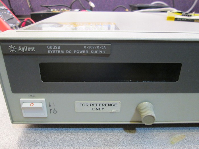
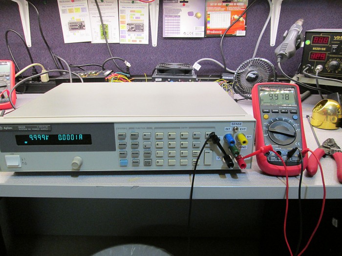
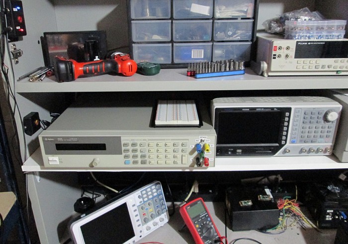
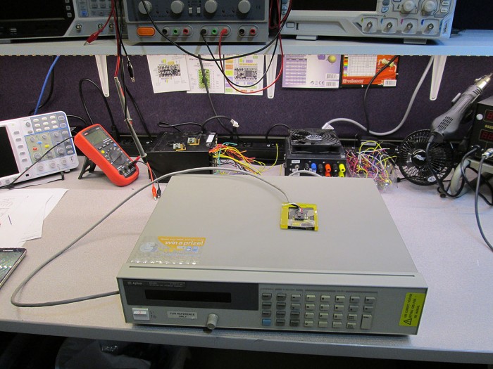
I picked up a “gently used” Agilent 6632B 0-20V, 0-5A Power Supply from Kijiji the other day. Seemed like a kick ass deal so I jumped on it. The power supply was in decent shape, a bit dirty but fully functional. This is my first pro grade DC power supply. Not only it is extremely precise, has remote sense, it can also act as a variable load and it can sink the same 5A that it can dish out.
IMG_1150

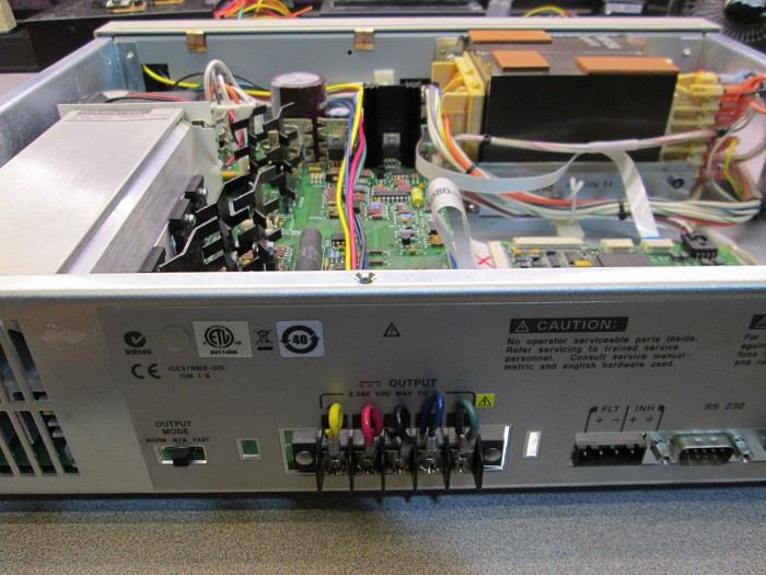
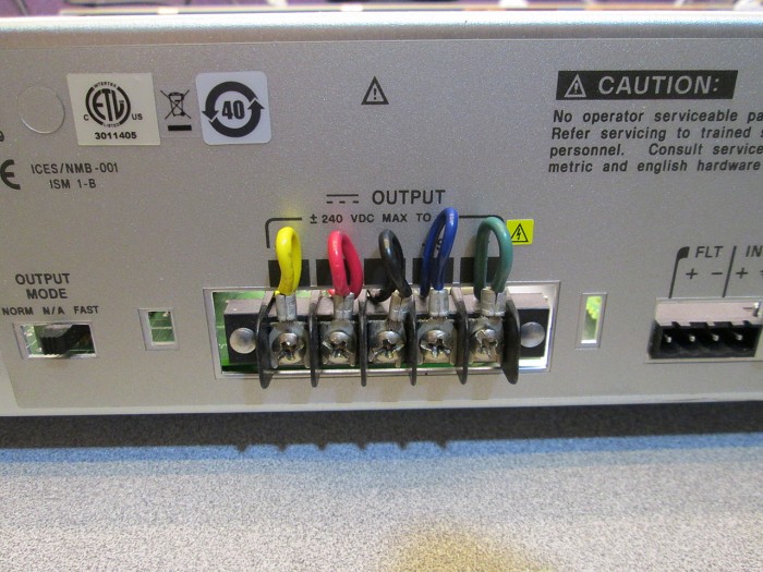
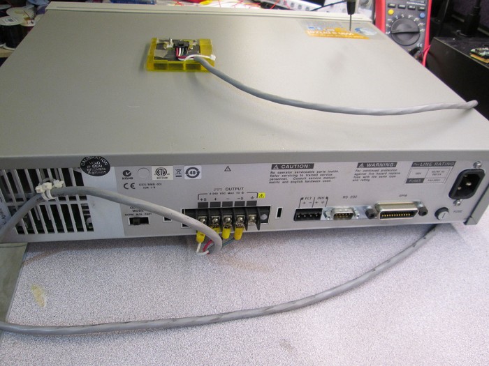
As this version of the power supply is meant to be used in a rack, the outputs are located on the back. Since I will be using it on the bench, I wanted front mounted binding posts.
IMG_1151

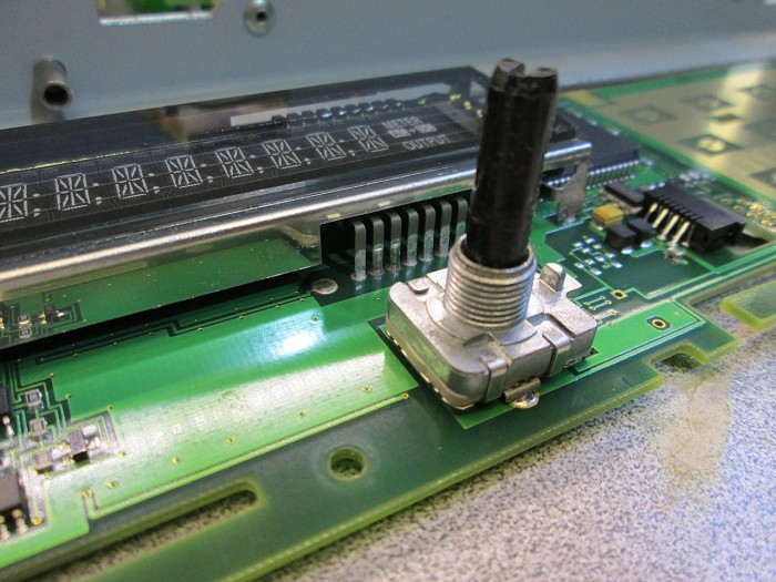
As I was cleaning the exterior of the power supply I noticed that the rotary encoder on the front was very wobbly. During power on testing it would intermittently not register the rotation. This was something I needed to fix.
IMG_1152

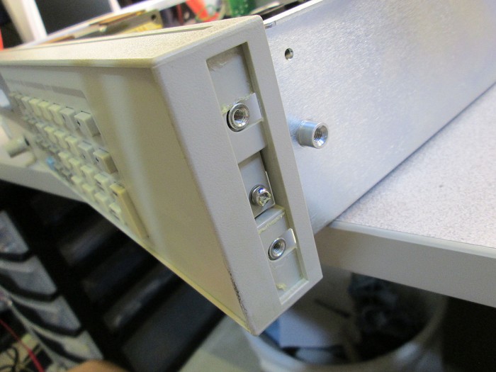
Removing the enclosure on the power supply is very easy. A few visible screws on the side and one screw on each side of the front panel that’s hidden behind a self adhesive strip.
IMG_1156

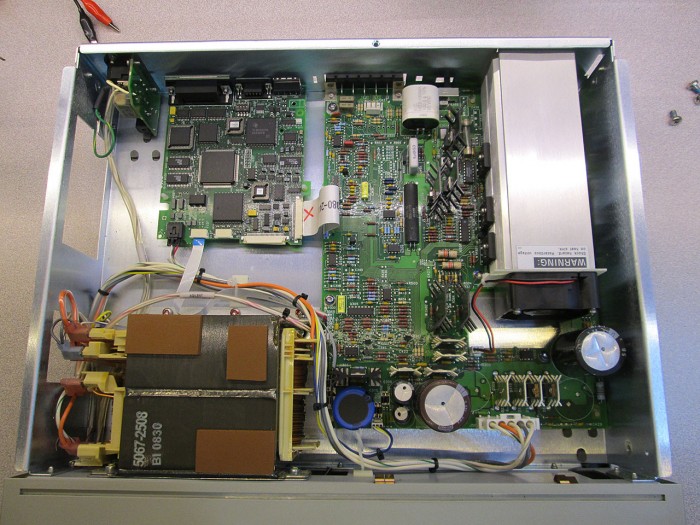
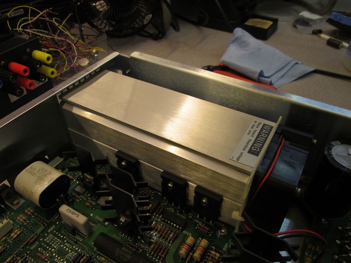
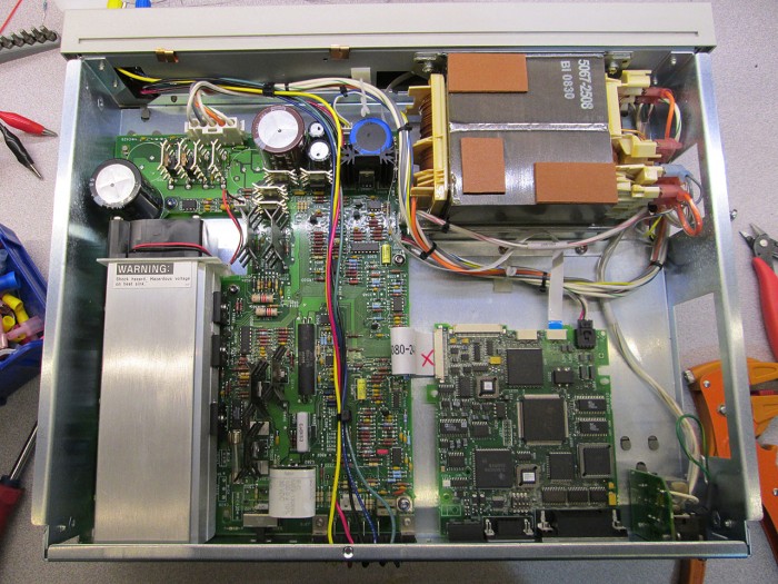
Love the interior of this thing. Massive mains transformer, huge heatsink to dissipate the 100W of load. Massive caps.
IMG_1154
IMG_1155

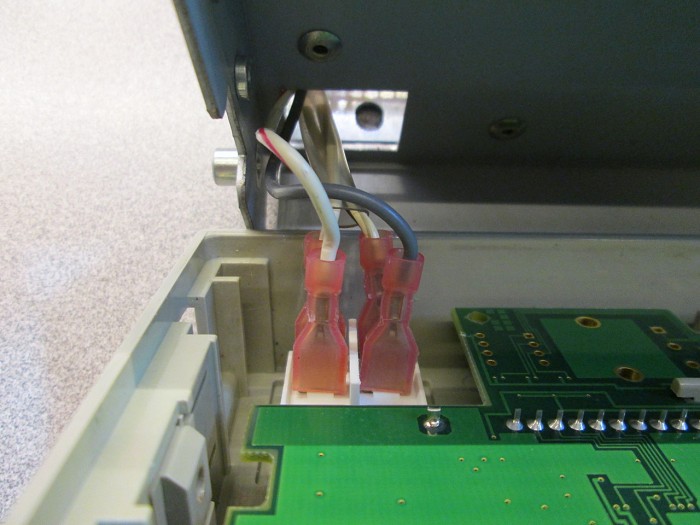
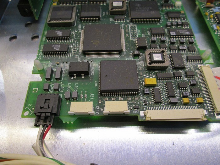
Disconnecting the front panel is easy. Just 4 wires to the mains switch and a ribbon cable to the back control board (J210 connector).
IMG_1157
IMG_1160

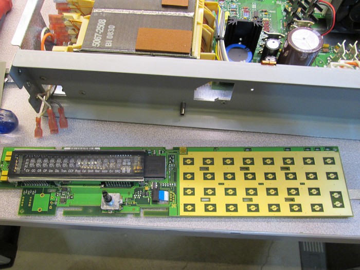
Once disconnected removing the control board from the plastic enclosure was just a matter of sliding it off to one side.
IMG_1161

Fixing the rotary encoder was very easy. The encoder is built from two parts held by pressed pins. The pins were loose and simply needed to be bent back to retighten the package. Easy stuff.
IMG_1162

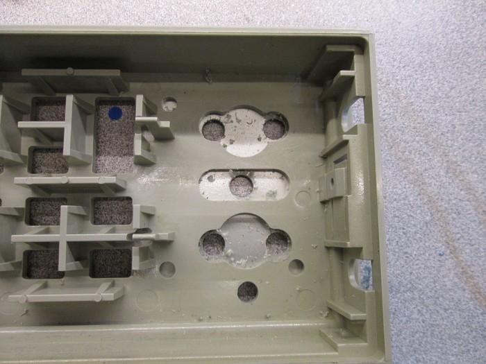
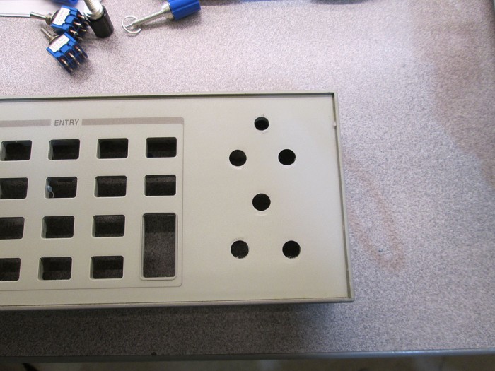
What was really surprising was the pre-cut holes in the front panel for binding posts. Looks like the same bezel is used in both rack mount and bench models. This makes drilling holes in the bezel easy and not much measurement required.
IMG_1166
IMG_1168

I had a choice of two types of binding posts to use. I have a premium set of posts that I wanted to use but I realized that the front panel is metallic so using mounting an all metal binding post wasn’t a very good idea. I chose the cheaper but still decent posts instead.
IMG_1169

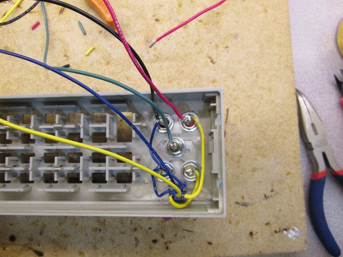
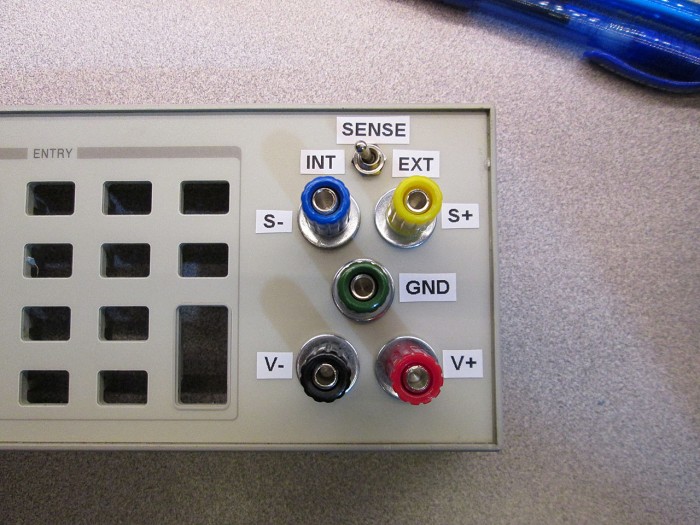
One feature I wanted to implement is to have a local/remote sense option without having to use jumpers which is what the rear panel was designed to do. Instead, I installed a DPST switch (actually DPDT cause I didn’t have the right one) to switch between sensing at the binding post terminals and optionally at the load with the additional binding posts. I used 16AWG stranded wire to which is more than sufficient to carry 100W between the front and back of the power supply. The sense wires could have been thinner but I wanted to keep the internal resistance as low as possible.
IMG_1175

Once the binding posts were and installed and the wires soldered on. I labeled the binding posts and switch positions.
IMG_1171

The rear connections were crimped using spade connectors. There was enough gap between the terminal strip and the enclosure to run the wires. Even though the edge of the enclosure is rather sharp I’m not too concerned about cutting through insulation as the power supply will see minimal movement.
IMG_1178
IMG_1177

Note: The sense wires should have been twisted to keep noise to a minimum. I didn’t realize this till after reassembling the power supply and the wires were too short to twist them so I just left it alone for now, I might fix this in the future
IMG_1181

Once the connections were made it was just a matter of reassembly and testing. And it tested perfectly. Easy job and now I have a kick-ass bench power supply.
IMG_1182

The depth of the Agilent enclosure is perfect. Not even 1/8″ of clearance between the edge of the shelf and the back of the workbench. Almost as if it were meant to be. Can’t wait to use this power supply on my next project (coming really soon)
IMG_1185

NAS/SAN Search 2014

It’s been a while since I looked at what’s new in the software/server based SAN/NAS world. Last time I looked was probably 2-3 years ago and I ended up with NexentaStor Community 3 as it was the most complete, stable and feature rich SAN OS at the time.

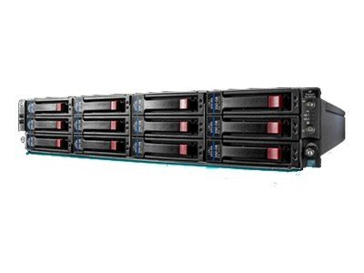
HP-ProLiant-DL180-G6-Server

Fast forward to 2014, there’s been tremendous developments in software based SAN systems, seems like days of Hardware RAID are numbered as pretty much every major SAN/NAS distro is pushing ZFS as the de-facto solution.

The goal here is to find a more up-to-date SAN so I can possibly replace NexentaStor in production assuming it offers more features or provides better performance.

Required Features:
* Email notification on disk failure
* Web UI managed
* High performance
* Stable
* NFS/CIFS(SMB)

Nice to have features:
* Embedded install (USB/CF)
* ZFS
* iSCSI (MPIO would be nice)
* Performance monitoring

Test Hardware:
HP SE316M1 (DL160) G6
1x Intel Xeon X5550
20GB DDR3 ECC RAM
6x 160GB 10K Velociraptors (to be replaced for prod)
1x OCZ Agility 60GB SSD (cache device, test use only)
Dual Intel NIC
LSI SAS2008-IT HBA (By Dell) or LSI 1068E-IR SAS HBA (whichever is supported)

On to the testing…

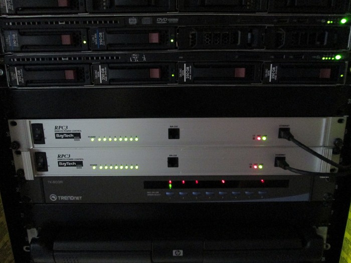
Baytech RPC3 Remote Power Controller

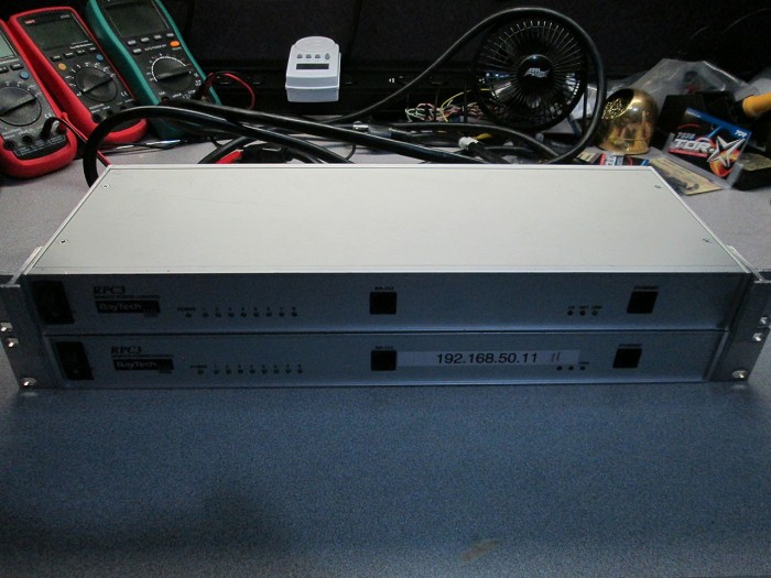
Thanks to another great find by members over at Serve The Home forums, I picked up a couple of Baytech RPC-3 remote PDUs for dirt cheap.
IMG_0833

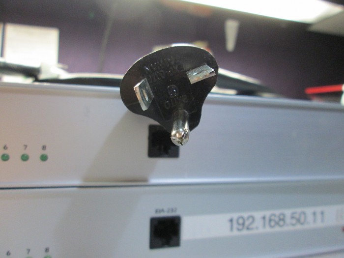
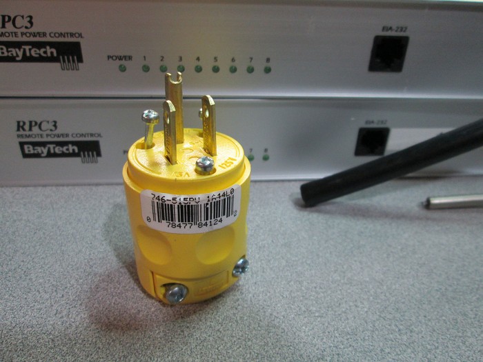
Even though the Baytech Units are rated for 20Amps and come with a 20 amp plug, my home feed is only 15A so first order of business is to convert the 20 amp plug to a standard 15A one.
IMG_0835

I picked up a couple of heavy duty plugs at Home Depot and went to work.
IMG_0836

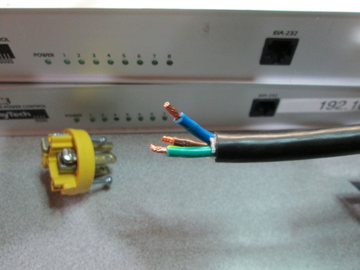
Simply cut off the existing plug and strip the individual wires
IMG_0837

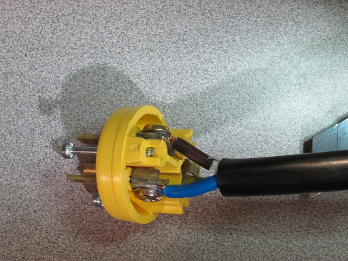
Then simply attach the wires to the new plug (make sure you get the Hot/Neutral/Ground right)
IMG_0839

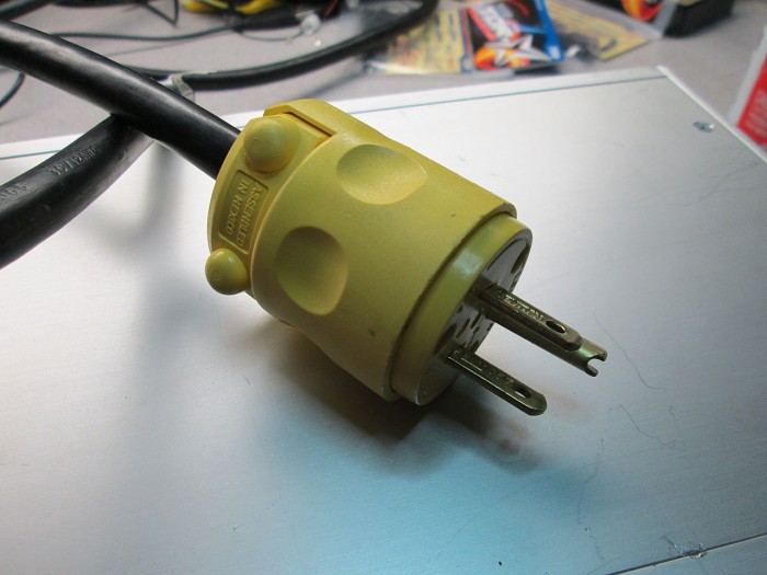
Reassemble the plug, all done.
IMG_0841

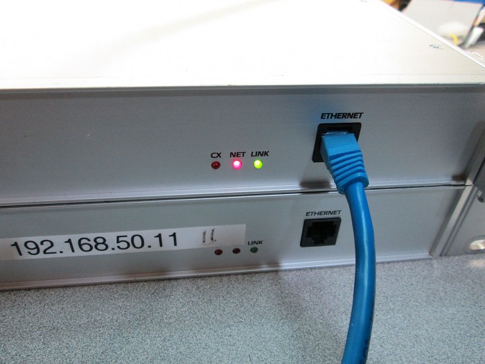
Once both units were rewired it was time to configure them. One of the switches didn’t come with an IP address sticker and I tried unsuccessfully to discover the IP address manually. It was becoming apparent that I’d have to configure the switch via serial connection.
IMG_0842

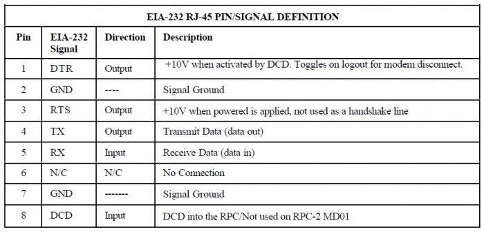
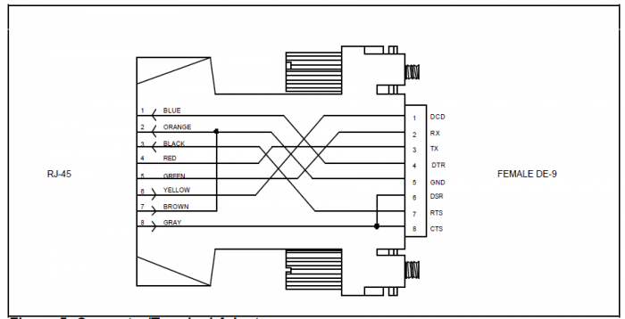
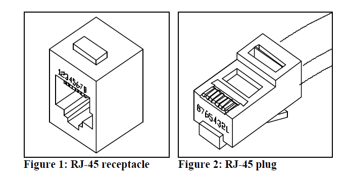
Unfortunately the baytech units use a non-standard DB9 to RJ-45 cable. Thankfully, Good Guy Baytech supplies the complete pinout in the manual so that you can make your own cable.
cable2
cable1cable3

Note: The diagram assumes that this cable will be used with a Null Modem (rollover cable) and is pinned out as such

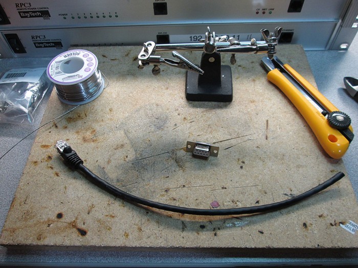
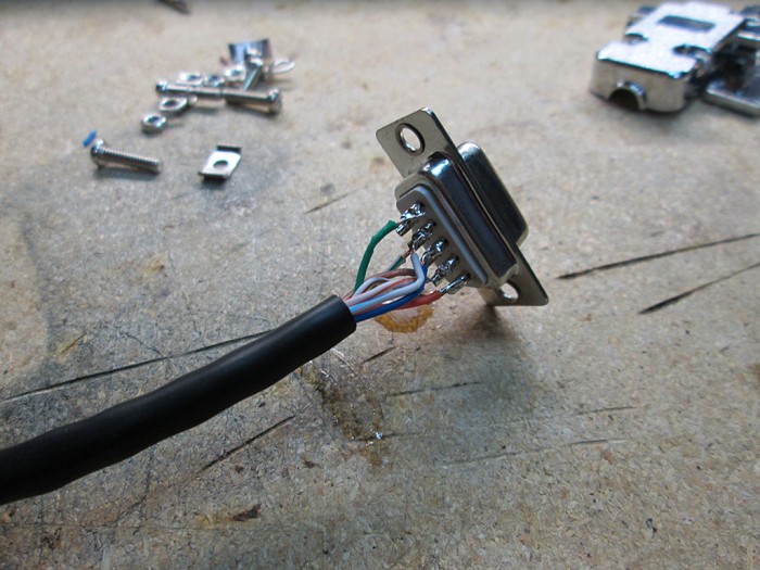
Making the cable is very straight forward. All that was needed was a short Cat-5e Patch cable, a female DB9 connector and some basic soldering skills. Simply cut the end of the patch cable, follow the pinout diagram and match up the wire colors in the opposite end of the cable to the proper DB9 pins. I ended up simply writing down the colors to pin matching so the soldering job went faster
IMG_0843
IMG_0844

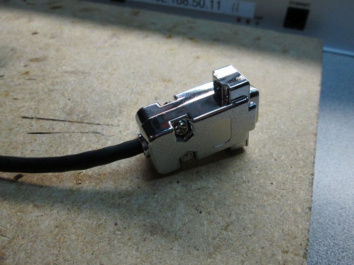
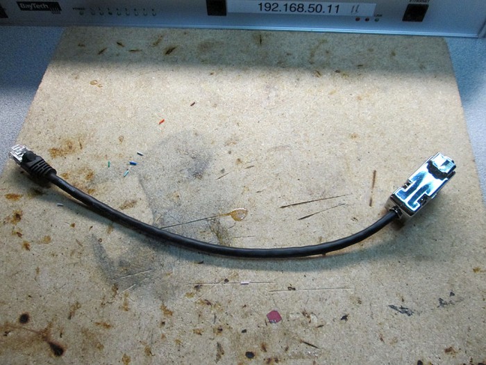
Few minutes later I had a working Baytech cable.
IMG_0846
IMG_0845

Fortunately the console was not password protected so it was easy to change the admin password. If however the console was passworded here are the reset instructions for Baytech RPC3’s

1. Turn off the power to the RPC3
2. Remove the lid
3. Locate JP1 on the Ethernet board
4. The jumper is placed on pins 1 and 2, move it to 2 and 3
5. Turn power on for 10 seconds
6. Turn power off
7. Return jumper to its original position.
rpc3_reset

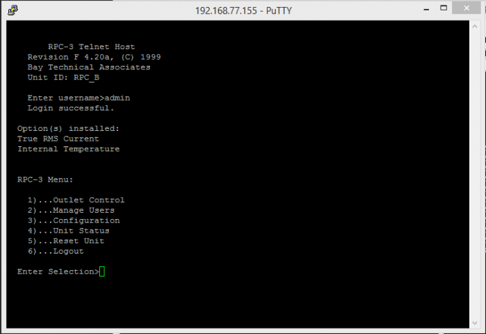
Once the IP address was configured via the serial console, the unit was ready for remote access
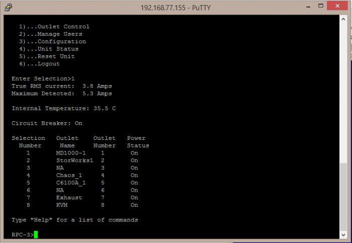
telnet
telnet_status

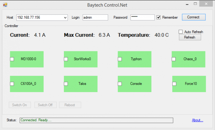
One last order of business before racking up the units was to provide a GUI driven interface for the unit. Since the RPC-3 uses basic command line telnet connection it was relatively easy to develop a basic app to control and monitor the unit remotely. Few hours of coding and I came up with a simple app that interfaces with the units.
BaytechControl
The app can control individual outlets by right clicking on it, or many at once by selecting the check boxes and invoking an action.

Link to App: http://www.copyerror.com/shared/BaytechControl.zip

Now it’s just a matter of racking it up and plugging everything in.
IMG_0858

The only complaint about these boxes is the master on-off button. I wish there would be some sort of cover over the switch as it’d be very easy to accidentally kill the entire pdu dropping all devices.

Manual: U140E125-05_rpc

Goodbye SugarSync

logo

In an effort to improve my security and privacy online I’ve finally dumped SugarSync for a self hosted solution.

I’ve spent a few months looking for an alternate solution to SugarySync, i’ve tried OwnCloud which turned out to be a real disaster and landed on Seafile.

While OwnCloud has a nicer GUI, it’s horribly buggy. The desktop sync client is slow and resource intensive. Plus I ran into an issue where two computers kept battling over same set of files (uploading/downloading back and forth) even though those files haven’t changed in years.

Seafile is for the lack of a better word, incredible. Very easy to configure, fast and comes with full mobile support. One of the coolest features is the ability to ignore files/directories by simply creating a seafile-ignore.txt file in the root of the library and adding whatever file masks to skip, a feature that SugarSync users have been asking for FOR YEARS. While not perfect (I’m running 3.0 Beta), it’s a pretty polished product and sufficiently stable to be used in production.

Incidentally configuring Seafile was also the first time i used Nginx as opposed to Apache. It’s going to be a while before I get comfortable with the configuration file format but so far I’m liking it.

I’m still looking for self-hosted alternatives for Evernote, LastPass and XMarks…the search continues.

RGB Fan Mod

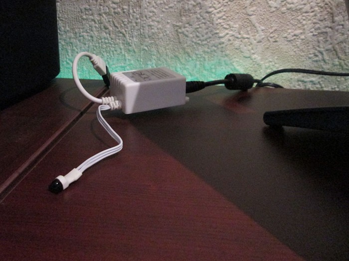
Few months ago I used some RGB LED lighting in my room (eBay China special). The setup uses an IR remote control and a control box to control the lighting. Power is supplied via a high current 12V power supply (10A supply)
IMG_0804
IMG_0802

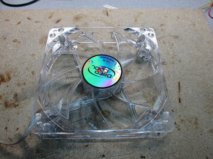
My “gaming” computer uses green LED fans which looks kind of odd when using any other color on the strip. Changing the color of the computer required swapping the fans for a different color.
IMG_0789
IMG_0788
IMG_0786

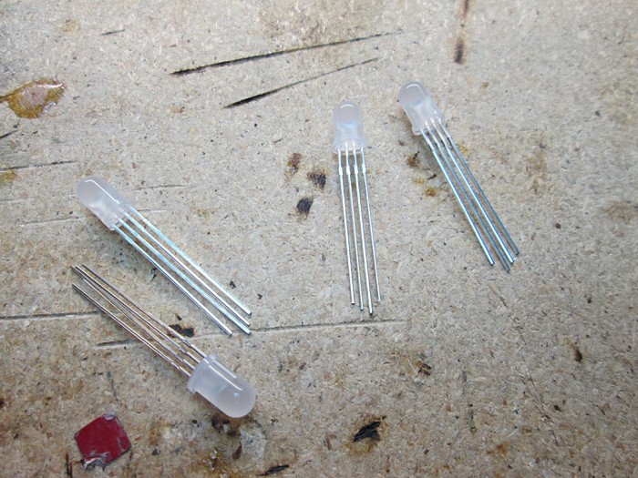
So, I decided to modify the fans to sync the colors of the fans with the rest of lighting. I already had tons of RGB LED’s, so it was really a matter of A LOT of soldering. One thing to note is that the LED ligthing system uses common Anode configuration, with a single 12V rail and 3 (RGB) grounds.
IMG_0746

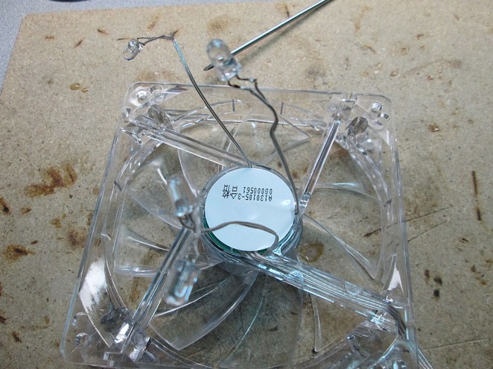
Once I pulled the fans from the computer, I had to remove the old green LEDs from the fan.
IMG_0741

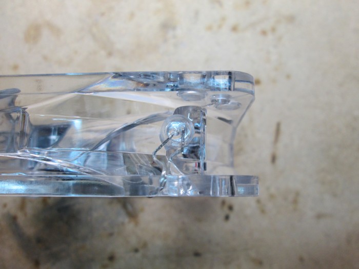
Fortunately the LEDs are simply pressed into place and not glued. This makes them easy to pop out with just a little bit of force.
IMG_0742

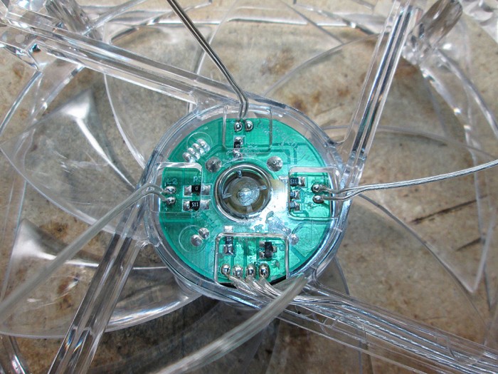
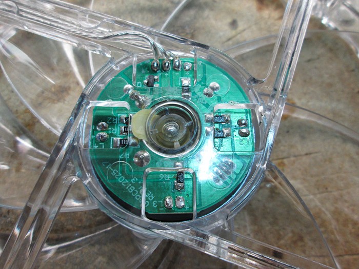
The leads for the fans are connected to a small circuit board underneath the sticker on the fan
IMG_0743
IMG_0744

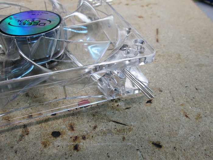
A quick application of a soldering iron and all the LED leads have been removed. Since the LEDs are no longer supplied with fan voltage rail, the brightness of the LEDs will no longer be tied to the speed of the fans.
IMG_0745

The RGB leds a just tiny bit larger than the original LEDs so it took a bit of extra force to press them into the socket.
IMG_0748

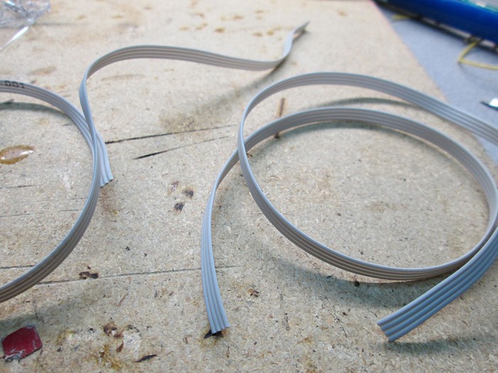
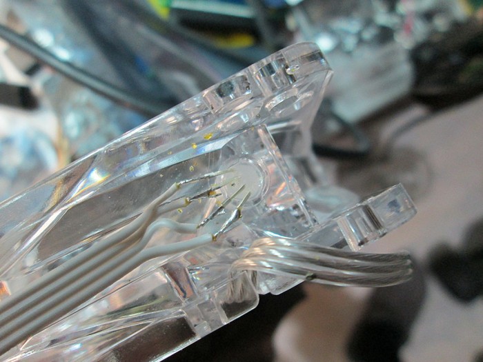
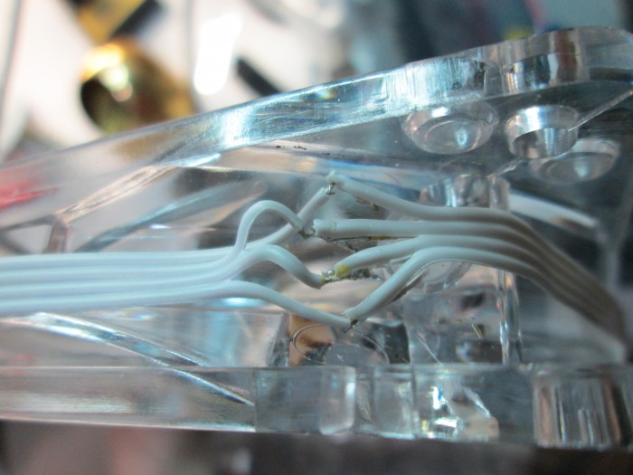
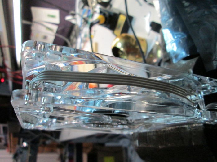
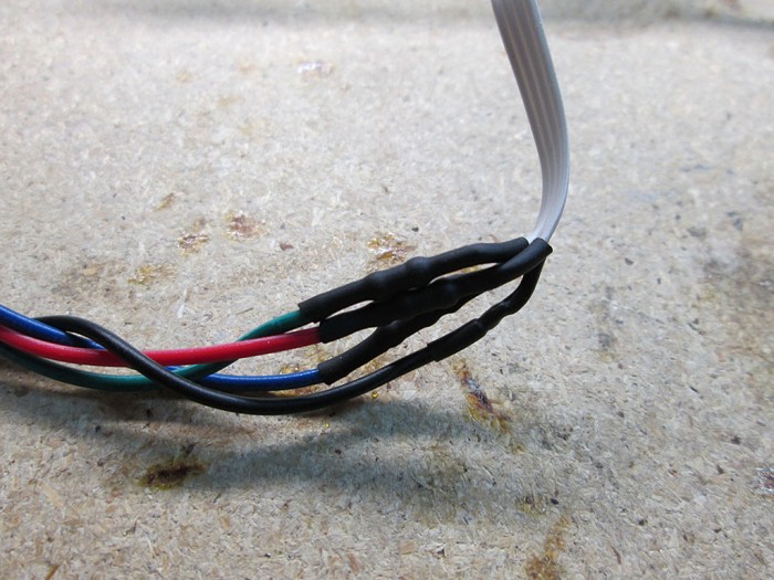
I used standard ribbon cable to carry the RGB voltages across the LEDs in the fan. The individual current for each fan is very low so the ribbon cable can easily handle the load.
IMG_0749

All LEDs were connected via point-to-point connections. This was actually a fair bit of work. The ribbon cable is quite delicate so I had to take extra care when stripping the wire ends as not to cut the lead.
IMG_0752
IMG_0754

The ribbon cable is nice and flat so it doesn’t affect the overall diameter of the fan much. Still, there would be certain configuration where the fans are too close to an edge where this would be problematic. Fortunately in my case, the fans are spaced sufficiently apart that the ribbon cable doesn’t interfere.
IMG_0755

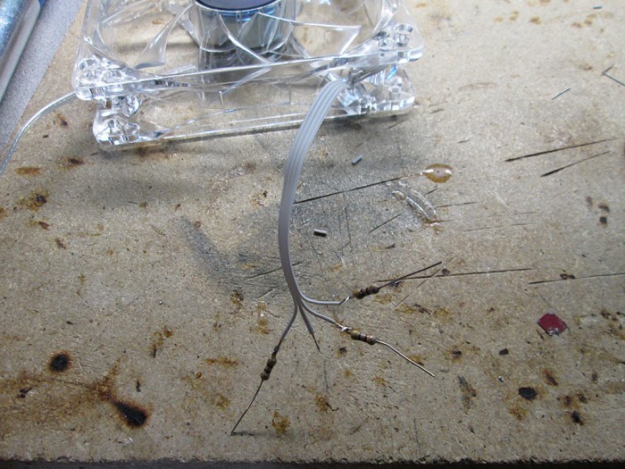
Once all the LEDs were electrically connected they had to be terminated via current limiting resistors. During bench testing I found that the 470ohm resistors provided the best brightness to current ratio at 12V. Since the LED receives power on a common Anode and each color draws slightly different amount of current, it’s important to place the resistors on the individual color leads. Putting the resistor on the anode pin will not work properly when using more than one color at a time.
IMG_0757

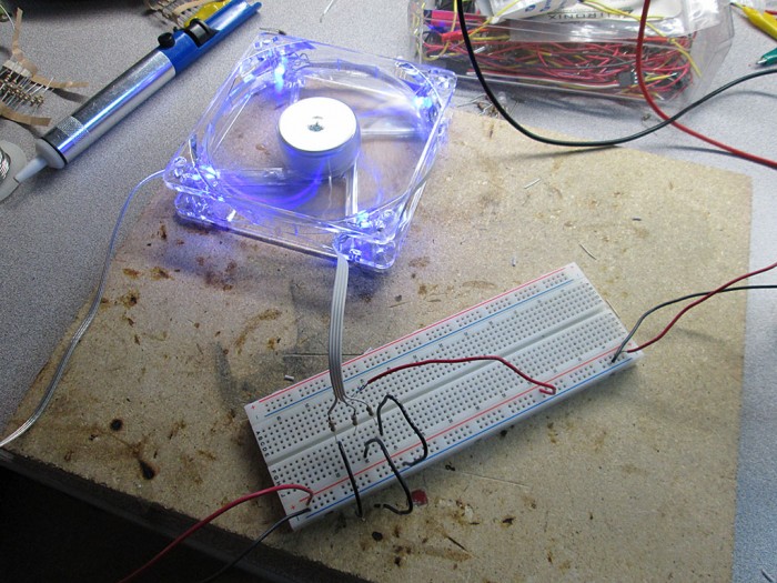
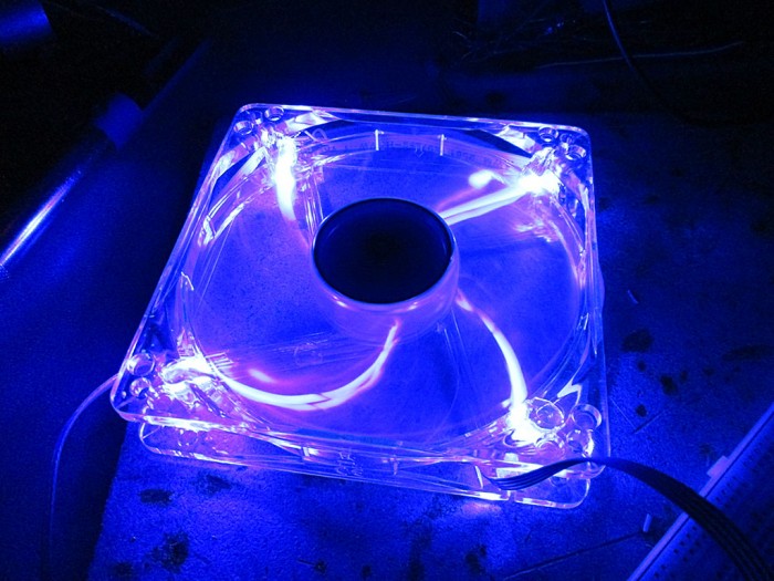
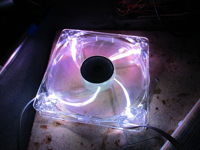
With the first fan completed I did some testing to see how the setup will stack up. I wasn’t sure if the RGB LEDs will be bright enough.
IMG_0764

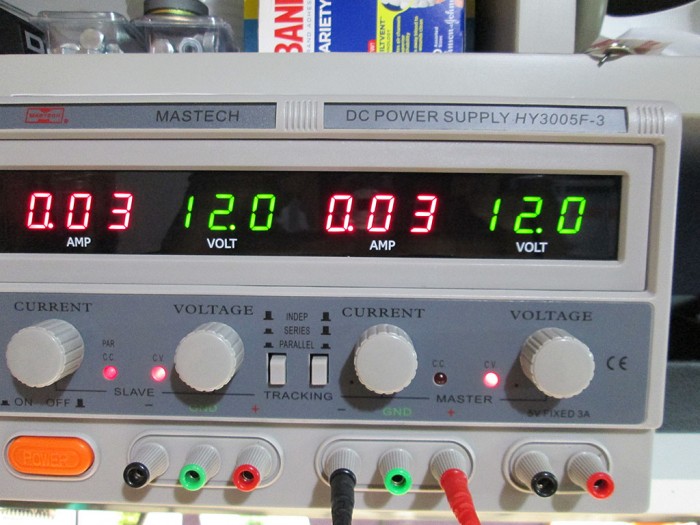
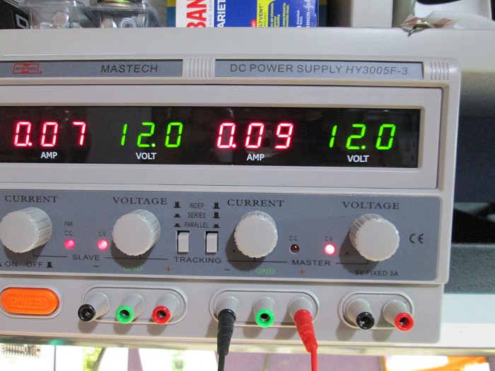
At 12V the individual colors only draw about 30mA per fan.
IMG_0758
IMG_0763

With all the colors lit, the draw was just 90mA. Which works out to under 500mA for the whole computer. A negligible load on the control box for the ambient lighting.
IMG_0765
IMG_0760

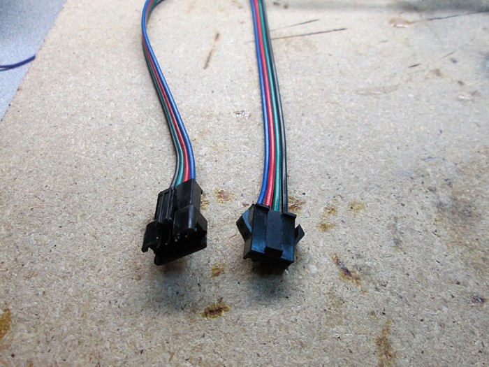
To connect the fans to the LED strip I bought some JST 4 pin connectors. It’s surprisingly difficult to find small 4 pin connectors locally, so I had to do another China eBay order and wait another month for them to show up.
IMG_0776

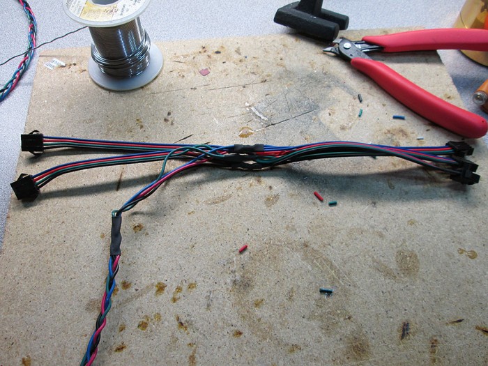
To complete the connection, all the resistors were then wrapped via heatshrink and soldered to the connectors. I gave each fan about 8″ of wire to make the connections between the fans easy.
IMG_0778

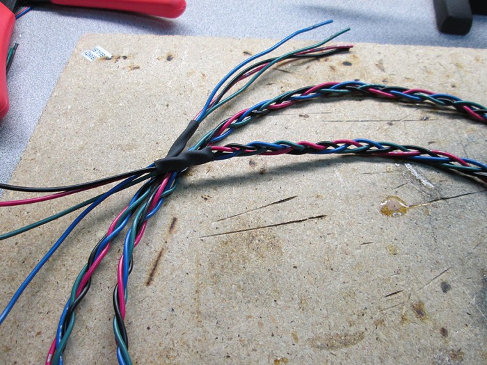
To connect all the fans together and to connect them to the LED strip I braided few 24 gauge wires to make a nice flat cable. This cable will run outside of the computer via a hole (meant for water cooling hose) in the computer case.
IMG_0781
IMG_0782

Once all the fans were soldered up, I installed them back into the computer. My wire organization skills are certainly not the best, but then again this is just a Mini ATX case so not heck a lot of room to stash the cabling.
IMG_0791

Last step was to connect the supply cable to the LED strip and turn it all on.
IMG_0794
IMG_0795
IMG_0799

Here’s a short video of the LED system, with the light mode set to cycle all colors.

VOIP at Home

asterisk-bubble
As part of a side project I jumped into the “exciting” world of VOIP and Telephony. Of course, as soon as someone mentioned VOIP or PBX I think Asterisk. Now, I’ve heard of Asterisk for years, and I’ve always considered setting up a PBX at home but I could never figure out how I would utilize the features on a day to day basis. Now that that side project has come up, it was the perfect excuse.

First thing first, I jumped on Kijiji and picked up a set of Cisco 7960G phones.
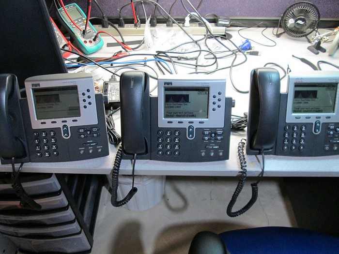
IMG_0766

The phones were in decent condition and already have been preloaded with the SIP version of the firmware. They were however each running different version of the firmware so first step was to factory reset these phones and update to latest available SIP firmware.
To factory reset the phone.

* Plug in the phone
* Hold # key until message …
* Press the following key sequence 123456789*0#
* Press 2 to delete network config
* wait for the phone to reboot

Updating firmware is pretty trivial. Once a TFTP server has been configured, simply drop the updated firmware onto the TFTP server and point the phones at the IP address. These phones automatically check for updated firmware on the server during the bootup process.

If DHCP option for TFTP isn’t configured, an Alternate TFTP server can be configured on the phone via Network Configuration. Before attempting to change the setting the phone must be unlocked via option 9. The default password for the phones: cisco

When the phone boots up it checks the TFTP server for configuration files. The two most important files are SIPDefault.cnf and SIP<mac>.cnf. These are two of the files that the phone will look for during start up to self-configure.

The SIPDefault is a great place to put common settings for all phones.
Example Format for SIPDefault.cnf

image_version: P0S3-8-12-00
proxy1_address: "voip.olympia.local"            ; Can be dotted IP or FQDN
proxy2_address: ""              ; Can be dotted IP or FQDN
proxy3_address: ""              ; Can be dotted IP or FQDN
proxy4_address: ""              ; Can be dotted IP or FQDN
proxy5_address: ""              ; Can be dotted IP or FQDN
proxy6_address: ""              ; Can be dotted IP or FQDN
proxy_register: 1
messages_uri:   "*97"
phone_password: "cisco" ; Limited to 31 characters (Default - cisco)
sntp_mode: unicast
sntp_server: "pool.ntp.org"
time_zone: "EST" ; assuming you're in GMT
time_format_24hr: 0 ; to show the time in 24hour format
date_format: "D/M/Y"  ; format you would like the date in
dial_template: dialplan
autocomplete: 0
call_hold_ringback: 1
#nat_received_processing: 0
logo_url: "http://voip.olympia.local/cisco/logo.bmp"
services_url: "http://voip.olympia.local/cisco/services.php"
directory_url: "http://voip.olympia.local/cisco/directory.xml"

SIP<mac>.cnf (SIP<MAC>.cnf replaced with actual MAC address of the phone)

#office phone

image_version: P0S3-8-12-00

line1_name: 100
line1_authname: "100"
line1_shortname: "Ext 100" ; displayed on the phones softkey
line1_password: "secret" ; replace with a strong password
line1_displayname: "THC Inc 100"; the caller id

proxy1_port: 5060
proxy1_address: voip.olympia.local

# Line 2 Setup
line2_name: 1000
line2_authname: "1000"
line2_shortname: "Intercom"
line2_password: "secret"
line2_displayname: "Intercom";

phone_label: "THC Inc.  " ; add a space at the end, looks neater

#remote access to the phone
telnet_level: 2 
phone_password: "cisco" ; Limited to 31 characters (Default - cisco)

# uncomment below to connect over the internet
#nat_enable: 1

#custom phone logo
#logo_url: "http://kermit/asterisk-tux.bmp"

user_info: none

Couple of great resources for Cisco config file:
http://wiki.siftah.com/Cisco_7960G_IP_Phone_on_Asterisk
http://www.jtech.net/ip_phone/cisco/7940_sip_config.aspx

There are two providers I’ve signed up with. VOIP.ms and CallCentric.com. Both provide support for SIP/IAX2 phones and have very low rates, which is great for someone who doesn’t use land lines all that often. Having two providers also adds failover for outgoing calls.

I’ve always known about Asterisk but I also found few derived projects like AsteriskNow (turn key distro) and Elastix which had a much more polished web GUI. There’s tons of articles on the web about configuring Asterisk/Elastix and it, in itself is pretty trivial. But there are quite a few gotchas, especially if the server is hosted and open to the internet. For this exercise I ended up with Elastix as it seemed more user friendly than AsteriskNow with the default FreePBX UI.

So, couple of items when configuring a web open Asterisk server.

* Make sure extension passwords are VERY strong.
Since the password is never entered manually (only in Asterisk config and TFTP file config). It can be made impossibly strong and long.

* Protect the server via fail2ban.
Fail2ban is a fantastic solution to brute force attacks. It simply scans the log file file for failed authorization attempts and then simply blocks the incoming connection at the firewall effectively shutting the remote address out. This makes brute-force attacks impractical since the attacker can only try 4-5 passwords / hour for every IP they have.

Elastix already comes with fail2ban pre-installed, just needs to be configured.

/etc/asterisk/logger.conf

[general]
dateformat=%F %T

messages => security

This will create a new log file /var/log/asterisk/message

Add the following to /etc/fail2ban/jail.conf

[asterisk-iptables]
# if more than 4 attempts are made within 6 hours, ban for 24 hours
enabled  = true
filter   = asterisk
action   = iptables-allports[name=ASTERISK, protocol=all]
              sendmail[name=ASTERISK, dest=email@domain.com, sender=fail2ban@yourdomain.com]
logpath  = /var/log/asterisk/messages
maxretry = 4
findtime = 21600
bantime = 86400

Create a new file /etc/fail2ban/filter.d./asterisk.conf

 Fail2Ban configuration file
# Author: Xavier Devlamynck

[INCLUDES]

# Read common prefixes. If any customizations available -- read them from
# common.local
before = common.conf

[Definition]

# Option:  failregex
# Notes.:  regex to match the password failures messages in the logfile.
# Values:  TEXT
#
#log_prefix= \[\]\s*(?:NOTICE|SECURITY)%(__pid_re)s:?(?:\[\S+\d*\])? \S+:\d*

failregex = SECURITY.* SecurityEvent="FailedACL".*RemoteAddress=".+?/.+?//.+?".*
            SECURITY.* SecurityEvent="InvalidAccountID".*RemoteAddress=".+?/.+?//.+?".*
            SECURITY.* SecurityEvent="ChallengeResponseFailed".*RemoteAddress=".+?/.+?//.+?".*
            SECURITY.* SecurityEvent="InvalidPassword".*RemoteAddress=".+?/.+?//.+?".*

# Option:  ignoreregex
# Notes.:  regex to ignore. If this regex matches, the line is ignored.
# Values:  TEXT
#
ignoreregex =

* Firewall issue (Extension UNREACHABLE)
There’s a potential issue when using extensions that connect to the host PBX via the internet. Specifically, shortly after the extension connects it’ll disconnect and Asterisk will report the extension as UNREACHABLE, even though the ping is less than 2000ms (default for qualify=yes).
Changing the value of qualify to higher numbers (i.e. qualify=6000) has no effect.

The problem is that by default Asterisk sends a keep alive command to the phones once every 60 seconds, a lot of firewalls will close the UDP socket within 60 seconds as part of cleanup. So, to combat this the fix is to change the default “qualifyfreq” on Asterisk to a value less than 60 seconds. I changed the value to 45 seconds and it seemed to fix the problem for me.
The file to modify is located at /etc/asterisk/sip_custom.conf.

Simply add the following lines to the file:

qualify=5000
qualifyfreq=45
keepalive=yes

This will ping all the connected devices every 45 seconds and it’ll wait 5 seconds for response before timing out.

Additionally, in pfSense go to: Firewall -> System -> Advanced -> Firewall/NAT -> Firewall Optimization Options and change the option to “Conservative”. This will increase the timeout for the UDP connections before pfSense considers the connection closed and removes the socket.

* Locking down Web Interface.
If you absolutely must have port 80/443 open to the web, it’s a good idea to move the default web site to a virtual hosted site as it’ll make it a bit harder for bots to discover the site since it can only be accessed via proper url.

* Cisco Phone Logo
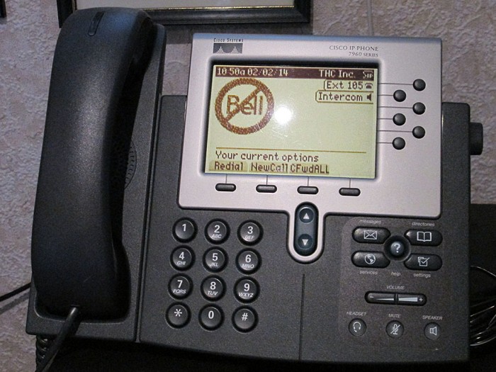
The logo image on the 7960G phones can be customized. It is a simple 4 bit image with a size of 90×56 pixels. The phone will automatically rescale larger images but it won’t look very good. I found the best way to save a compatible image is to use MS Paint and save the image as 256 color bitmap. The 7960G will also attempt to dither the image to display different shades.
IMG_0775

* Intercom System / Paging
This turned out to be more a challenge than I originally thought. Cisco SIP firmware doesn’t officially support paging so a workaround is to configure a line with auto-answer capability and then create a paging group in Elastix. Even though the 7960G has auto_answer configuration option, this feature can not be enabled via the config file and has to be manually configured on each phone. Not a big deal when dealing with a dozen or so phones, definitely an issue when dealing with large deployments.
Minuteman RPM1601 Smart Power Switch

I did another border run recently to pick up some more eBay goodies.
IMG_0701

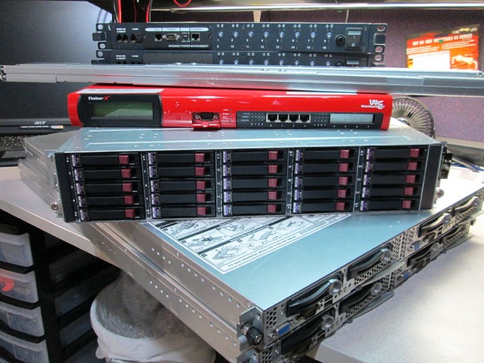
Over the last month or so I scored some incredible deals on server hardware. Picked up a couple of Intel SR1680MV Dual node servers, my favorite in 1U config right now. A really cheap HP Storageworks MSA70 with 25 Trays and some other items.
IMG_0702

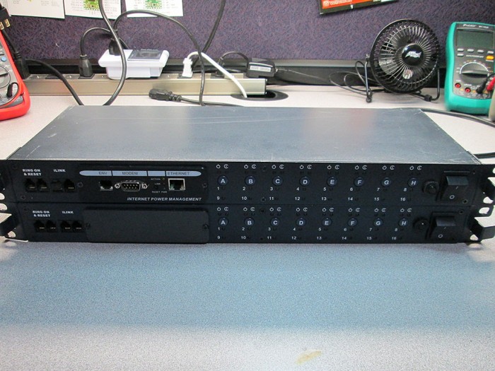
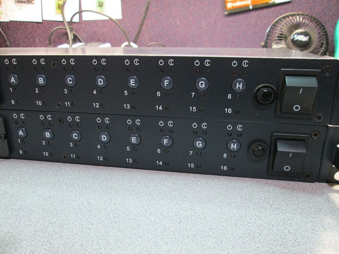
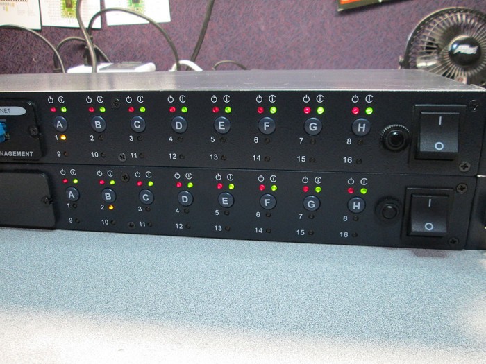
Also picked up a pair of Minuteman Remote Power Management switches. These babies use to sell for over $800 a piece, I picked them up for about $20 each. Now granted these are most likely VERY old devices. I’ve never heard of Minuteman but for that price I was very much willing to give them a shot.
IMG_0706

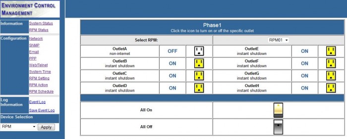
Each switch can manage 8 power ports. Each port can be designated for remote operation (via HTTP, Telnet or SNMP) or local only.
IMG_0707
IMG_0711

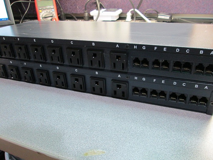
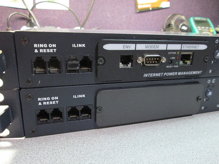
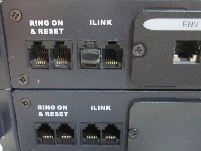
The switches come with 8 power ports each rated for a total of 12A @ 120V. Unfortunately the switches do not report actual power draw at port or total. Each power port comes with it’s own RJ11 port that can be use to interface with a respective UPS or Computer, a feature I’ll most likely never use.
IMG_0709

The switches were both “supposed” to come with a management card but the seller screwed up and sent me only one. Since I already considered this a pretty good deal I didn’t want to send them back even though the seller offered a full refund.
IMG_0708

The lack of a second management module isn’t a big deal since these devices can be chained and managed from a single card, but more on that later.
IMG_0712

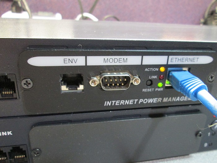
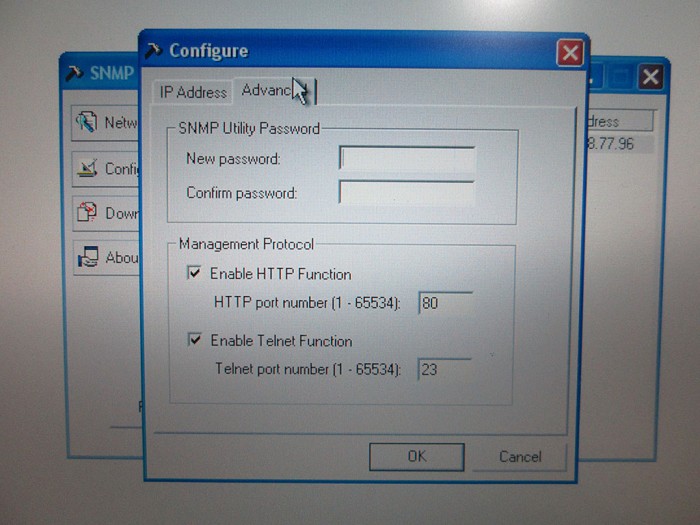
First order of business is to try to log into the thing. Unfortunately the devices came with no instructions or passwords of any kind. So, I connected the switch to my lab network and checked to see if by any chance the device is set for DHCP. No luck, DHCP lease list didn’t show any new devices on the network. A quick search for a manual on the Minuteman site and I came across SNMP based discovery snmp32_utility.
IMG_0710

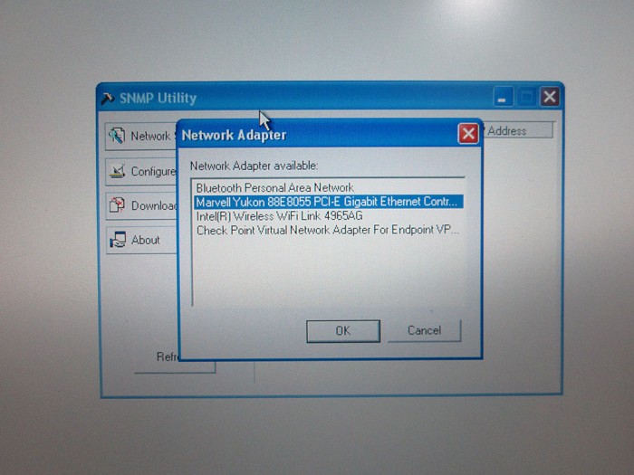
Once again ran into a small issue as the software doesn’t seem to work under Windows 7 and up (network list is empty).
IMG_0720

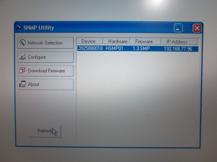
Fortunately I have an old toughbook kicking around that has Windows XP 32 bit installed. A quick install and bingo! the device shows up. Attempting to access the device resulted in a password prompt. Once again I lucked out since the password was simply set to “admin” and it only took me 3 tries to figure it out.
IMG_0721

I cleared the password and set the device for DHCP.
IMG_0722

Once web access got enabled I fired up my browser and pointed it at the device IP. Crap! Another password prompt. This time no amount of defaults was able to bypass this login screen.
login

Fortunately, through a lot of web searching I found a procedure to factory reset the management card which clears any passwords on it. The process is as follows

* Remove the screws holding the management card in place
* Using a small tool press the "Reset" button on the management card and hold
* While holding the reset button pull the management card out of the switch unit
* Continue holding the reset button, wait a few second then re-insert the card to power it up.
* Continue holding the reset button for another 40 seconds and release.
The management card has been fully reset.

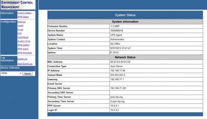
Once the card resets, reconfigure the card for DHCP again and use blank login/password on the site credentials and *boom* we’re in.
web
web2

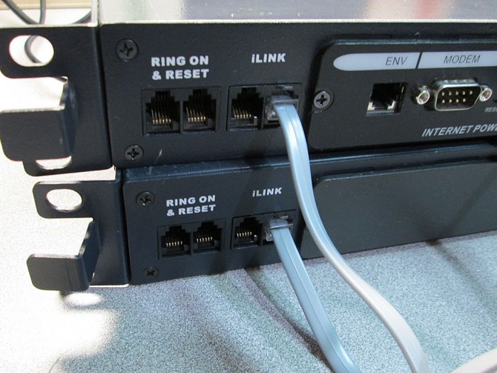
Now that we have access to the card, time to figure out how to chain the two. Based on the manual for the device. The switch comes with an “iLink” cable and a terminator plug. I received no cable and only one plug.

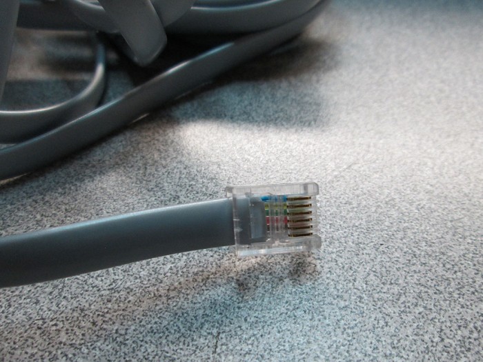
I picked up a 6 lane RJ11 cable and plugged it into the boxes as described by the manual. However, no matter how I placed the cable and the one terminator plug, the device would never see the second box.
IMG_0717
IMG_0718

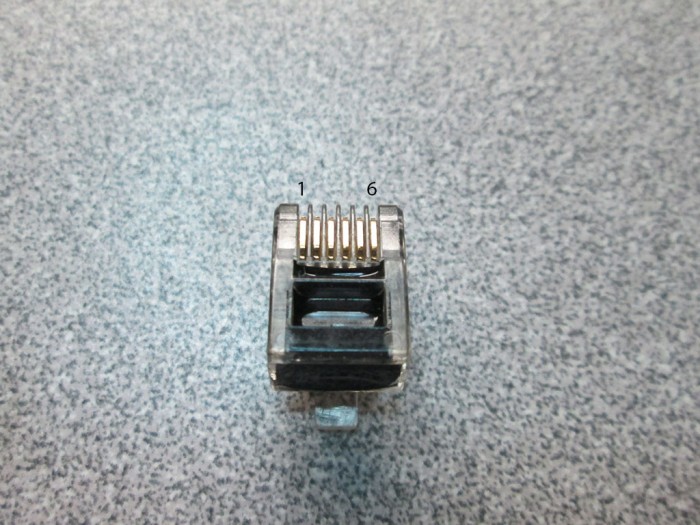
My first assumption was that I need a second terminator plug to close the loop. Since I only had one I decided to figure out how it works and build another one. I was pretty sure that due to the small size of the plug only passive circuitry is used inside. A quick run-through with a multi meter confirmed my theory and I determined the internal connections in the plug.
IMG_0715

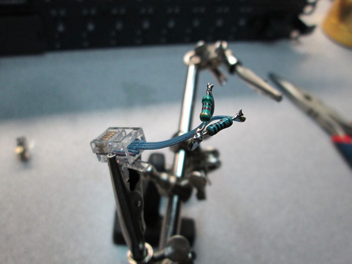
The pins on the terminator plug are simply connected via 1K and 5K resistors.
circuit

All I had to do was build a similar plug. I quickly whipped up a ghetto plug for testing and confirmed that it works since the master switch behaves slightly differently with it plugged in.
IMG_0725

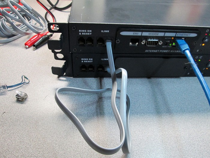
Once again ran into a roadblock. The addition of the second terminator did not result in connectivity between the two switches. Upon closer inspection of the cable I realized that the wires in the cable are not straight-through but rather reversed.
IMG_0717

I snipped the cable, reversed the wires and put another RJ11 plug on it and EUREKA! Both switches are accessible via the management interface. It also turns out that the terminators seem to be unnecessary in this configuration as the switches had no problem operating with the terminators removed.
IMG_0726
IMG_0723

I will probably toss these into one of my data centers where I’ll be able to reboot machines without having to drive for over an hour.

Files for this product:
snmp32_utility
SNMP-32-SL_manual
RPM_manual

New RC Car – Vaterra Kemora

A while ago a buddy of mine introduced me to a small 1:14 scale rally car. The Vaterra Kemora.
url

It’s decently well made, small RC car that comes with a brushless motor (4500KV) and even a Spektrum 2-channel radio. All for under $200. What really amazing about the price of the kit is that the individual replacement parts add up to much more than $200. It’s actually cheaper to buy another Kemora kit than order individual parts. This is just the perfect car for a small indoor track, like one we found locally not too long ago.

The biggest expense on my part was getting a few batteries for the car. While a lot of cheap options exist. I opted for the Traxxas #2820 2S Lipo packs. They fit the battery cavity well and provide healthy amount of capacity for nice long runs. Unlike a lot of cheaper batteries, they seem to keep their balance a lot better across cells and do not require balancing with every charge.
IMG_00000388

The car does have some minor issues though.

Tires
The local track uses silica covered painted concrete floor. Very harsh on the stock tires. The stockers went bald after only few batteries. Between few friends and I’ve tried several tire/wheel combinations that would last at the track and still give relatively good grip. I found the perfect combo! Duratrax Slicks (DTXC9722) and Wheels (DTXC9881). One of the cheapest and toughest combos we’ve tried yet. I have countless laps on these tires and a lot of contact between other cars and the walls and both wheels and tires are holding strong. Unlike a lot of slicks which are very plasticky, these tires are made from very sticky rubber. Even on the silica floor they provide just enough grip to go into corners fast but with just a blip of the throttle allow for easy drifts.
IMG_00000382

Other Issues
The motor runs very hot even on 2S batteries. We’ve seen upwards of 190F on the motor after a full battery run. I can’t imagine how this motor is to survive running on 3S. A motor heatsink is definitely recommended though due to the space constraints it might be difficult to find one that will fit. Currently running without the Chassis Cover to help keep the ESC and motor cooler. Will keep a lookout for a decent heatsink for this.

Another minor issues is the front axles have a tendency to pop out in minor collisions. The axles use a dog-bone design that takes a little bit of force to pop back in without having to take the tire off. It’s more annoying than anything, fortunately Vaterra offers upgraded axles that do not have this issue.

Lastly, the NiMh battery that I got with the truck was completely dead. It had an actual capacity of about 250mAh and cycling the pack repeatedly was not enough to bring it back to life. Not a big deal on my part as I was never planning to run on NiMH but again, something that Vaterra should address.

Issues aside this car is incredibly fun to race. And after countless laps and countless of collisions and rollovers, not a single part has been broken yet. It’s amazing actually as we’ve had some rather bad wrecks.

Update
After few hundred laps the stock body was getting pretty beat up (too many collisions). I got a new blank body and painted it. Added some nice lights by using 0.5W Ultra Bright 8mm LEDs for front and rear. Unlike my flasher project, these are just running lights.
IMG_00000390

I’m really digging this car. It’s a lot of fun to race for very little investment. And since it’s waterproof, it simply takes a quick hot shower in the sink at the end to clean it off. Hats of to Vaterra for this. Sounds like Traxxas has some real competition to their 1/16 Rally VXL.