High Voltage Madness

Back in late 90’s I built my first Tesla Coil. It was a totally amateur job on a very tight budget. The Tesla coil was powered with 2 12kV NST’s, yet it could at best output 20″ streamers. Partly due to horrible coupling and the really crummy Beer Bottle Capacitor bank that had a tendency to explode individual cells on extended runs.
Skip ahead years later. I wanted to take another stab at it. I decided that I wanted to re-use the original NST’s from the original build and see how much better I can do.
I begun the build by building the MMC Tank.
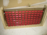
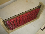
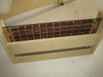
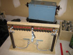
The tank capacitor MMC (Multi-Mini-Capacitor) bank. 98 Polypropylene Panasonic capacitors (ECW-H 16563JV) rated at 0.056 uF @ 1600Vdc.
8 Strings of 12 Caps each giving me 38.3nF @ 19,200 Volts. Each capacitor has a 10Mohm 1/4W bleeder resistor to discharge the caps after power has been cut. This is purely a safety feature. I’ve used a sheet of polycarbonate lexan as a board for this cap bank. I could not find a project board big enough to handle this many components and I wanted a lot of room between caps for additional cooling.
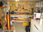
Quick look at my workshop. This is where I built the coil. It’s a good thing I started building it in early May, by June it was awfully hot outside. The coil took me approximately a month to build, roughly 3-5 hours per day.
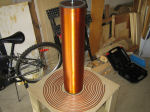
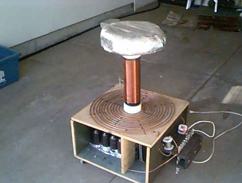
Test fit of the secondary to the primary. The primary is 13 Turns of 1/4″ copper tubing. For a total length of 50′. I’ve used zip-ties to secure the coil to the base. When constructing the tesla coil. No metal parts can be used other than the components themselves.
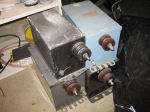
My power supply bank. Currently I’m using 2 12KV neon sign transformers at 60mA each. I’m trying to source more for possible unpotting. I’m curious to try unpotting to boost the output current beyond 100mA. NST’s have shunts for current limiting. Boosting power is as easy as removing some of the shunts. The hard part is getting to them.
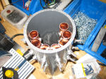
The Richard Quick/TCBOR style spark gap. Originally 7 1″ pipes cut to 4″. I didn’t like how the spacing between the electrodes came out. I’ve since changed it to 4 pipes with wider spacing. The vacuum motor is used for quenching the gap. I’m hoping to replace this with a rotary gap, ideally a synchronous type.
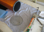
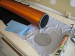
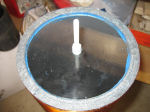
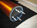
I’ve cut 2 lexan disks to seal the ends of the pipe. I’ve used nylon bolts and nuts to fasten the secondary to the base. I’ve used extra long bolts to allow me to adjust the coupling between
the primary and secondary by simply adjusting the nuts. I’ve used silicone sealant to secure the lexan to the PVC pipe.
I’ve added a strike ring above the primary coil. This ring is connected to ground and protects the primary coil from streamer strikes.
I’ve used a Terry Fritz NST filter as additional protection. The filter is designed to supress surges using either the safety gap or the Metal Oxide Varistors (MOVs). The Capacitors and 1k Ohm 100W Resistors filter kickback RF current from entering the NSTs.
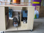
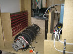
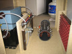
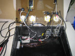
A test fit of the Tesla components under the coil. I was seriously considering building a separate power supply box that would house the NST’s and the filter away from the coil. If I add another NST supply, I’ll have to move them separately as there’s just not enough room under the coil.
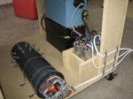
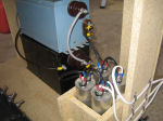
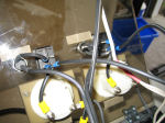
First interconnections completed. I’ve used Power Factor Correction caps to smooth out the power coming into the coil. The caps are 70uF @ 360V Motor Run type. They’re connected in 2 in parallel going into each transformer. I’ve kept the connections as short as possible. All connections in the coil are done using either ring or flat terminals. I’ve wanted to build this coil to the best of my abilities, no shortcuts allowed.
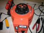
A 0-140V 20A Variac I purchased on Ebay from a local seller. Picked it up myself, shipping of this heavy beast would be astronomical. This variac effectively boosts power to the Tesla coil. As someone once said “Variacs are gods gift to Tesla Coilers”
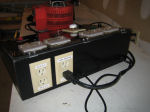
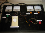
The control panel. I’ve wanted to build a proper and SAFE control panel that will allow me to fine tune the Tesla Coil operation. Built out of 5/8″ particle board. With a polycarbonate panel top.
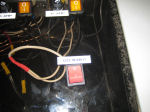
I’ve used a dremel tool to cut out all holes for the components. I’ve planned this control panel since I started working on the coil in the first place. I drew several variations of the schematic diagram before settling on the current design. Once again all connections are done with crimp connectors or ring/flat terminals. All connections inside the control panel are grounded to house ground. However all 120/140 connections to the coil are NOT grounded at the control panel, rather they’re grounded at the RF ground.The control panel has 4 fuses, 1 main fuse (20A). 15A fuse for the vacuum motor (really only need about 8). And 15A fuses to each NST. The NST’s draw about 10A each at run time, the vacuum draws about 5A. The total amps meter is mostly pegged when running the coil. I’ll need to replace it with a 30A or 50A meter. The Red switch is a momentary trigger switch, another safety device. All power to the coil is shut off as soon as the button is released.I’ve used a light dimmer rated at 600W to control the speed of the vacuum motor.
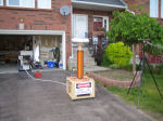
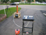
The coil rolled out and ready to fire. Initially the coil was tapped at 8th turn as calculated. However, somewhere I must have missed something because it’s actually tunning at 12th turn. That’s quite a big difference, not sure where the deviation is coming from.
| Coil Stats | |||||||||||||||||||||||||||||||||||||||||||||||||||||||||||||||||||||||||||||||||||||||||||||||||||||||||||||||||||||||||||||||
|
|
||||||||||||||||||||||||||||||||||||||||||||||||||||||||||||||||||||||||||||||||||||||||||||||||||||||||||||||||||||||||||||||
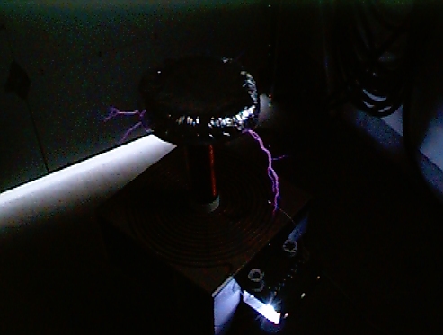
Some Videos of the Run
